background image

  11

OPERATING INSTRUCTIONS
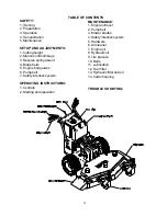
CONTROLS:

1. Be thoroughly familiar with all controls their function and how to operate them before
operating the mower.

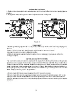
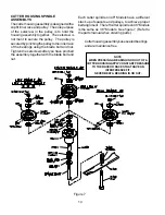
2. Control levers: Located on each side of the handle control direction of movement. The left lever
controls the flow of oil from the left hydro pump to the left wheel motor. The right lever controls the
flow of oil from the right hydro pump to the right wheel motor.

3. Ground speed lever: Located in the center of the console. Controls the forward speed of the
mower. Push the lever forward if you want to go faster, pull it back to go slower or pull it all the way
back to the neutral or stop postion.

 NOTE: To begin motion the operator must move the ground speed lever forward before disen-
gaging the thumb latches. After you release the thumb latches allow the control levers to move
forward at the same time. The mower will move in a straight line in that direction.
Movement of the right control lever forward will cause the right wheel to rotate in a forward direc-
tion. Movement of the left control lever forward will cause the left wheel to rotate in a forward
direction. To stop forward travel pull levers back into the neutral position.
To turn right while moving in a forward direction pull the right control lever back towards the
neutral position, this will slow the right wheel and cause the mower to turn in that direction.
To turn left  while moving in forward direction pull the left control lever back towards the neutral
position, this will slow the left wheel and cause the mower to turn in that direction.

4. Blade engagement lever: Located on the left side of the console.  To engage the blades push
the lever all the way forward and to disengage the blades pull the lever back against the console.

5. Choke and throttle control: Located on the right side of the console. Push the throttle control all
the way forward for choke. Use when starting cold engine do not run choke when engine is warm.
Use the throttle to control the engine RPM.

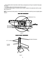
6. Tracking knob:  Located on the left back side of the console. If the mower will not travel in a
straight line on a smooth surface, turn the tracking knob the proper direction until it straightens
out.

7. Key switch: Located on the console. The key switch must be turned on, blades disengaged,
and ground speed lever in neutral before starting.

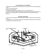
8. Fuel shut off valve: Located under the fuel tank.

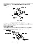
9. Pump release valves: Located at the back left corner of the pumps. Used to release the sys-
tem so unit may be moved by hand when not running.   NOTE: Only rotate about a 1/4 to 1/2 of a
turn to release system.

10. Operator presence levers: Located on the handle. One or both levers must be pressed against
the handle for the mower to remain running, when the blades are engaged or the ground speed
lever is not in the neutral position.

Summary of Contents for KHKW36140

Page 1: ...ow the important safety instructions and the other instructions contained in this manual Lawnmowers and all power equipment can be potentially dangerous if used improperly SAFETY REQUIRES GOOD JUDGEME...

Page 2: ...ey and operating instructions WARNING Failure to follow cautious operating practices can result in serious injury to the operator or other persons The owner must understand these instructions and must...

Page 3: ...Lubrication 12 Fuel filter 13 Hydraulic filter and oil 14 Cutter housing TROUBLE SHOOTING SAFETY 1 Training 2 Preparation 3 Operation 4 Transportation 5 Maintenance SETUP AND ADJUSTMENTS 1 Cutting hei...

Page 4: ...an off any spilled gasoline before starting the mower OPERATION 1 Mow only in daylight or good artificial light 2 Do not operate the mower in wet grass if possible 3 Mow across slopes Use extreme caut...

Page 5: ...USTMENTS 1 Uncrate mower 2 Mount front caster assemblies to the front deck using the fasterners provided on the deck both sides 3 Cut the plastic wire ties holding the operator presence levers down 4...

Page 6: ...see fig 2 NOTE To achive the best quality cut the blades should be level with the ground or slighty tipped forward CASTER SWIVEL 1 2 C SPACERS MACHINERYBUSHING CASTER HEIGHT ADJUSTMENT CASTER HEIGHT A...

Page 7: ...1 2 3 4 5 B A C MOTION CONTROL ADJUSTMENT 1 This adjustment must be made with the drive wheels rotating Raise rear of the unit and block it up so the wheels are free to rotate CAUTION Keep hands feet...

Page 8: ...peed lever should be in the neutral or stop postion and the thumb latchs unlocked 4 Loosen the two 1 4 bolts holding the reverse detent bracket Slide the bracket up or down till it just touchs the L s...

Page 9: ...e engagement lever is in the engaged position 5 To increase belt tension rotate turnbuckle toward the rear of the mower until desired tension is gained Do not over tighten belts to much tension will r...

Page 10: ...starting if the blade and or ground speed lever are engaged It also causes engine shutdown if the operator falls from or attempts to leave the operator position while the blades or ground speed lever...

Page 11: ...will slow the right wheel and cause the mower to turn in that direction To turn left while moving in forward direction pull the left control lever back towards the neutral position this will slow the...

Page 12: ...e dipstick and wipe clean Reinsert the dipstick all the way but do not screw down Remove the dipstick and check oil level If oil level is low add oil Use engine manufacturers specs for type of oil 2 P...

Page 13: ...se only 20w 50 motor oil 9 Tire pressure Check every 25 to 50 hours Rear tires require 15 psi and caster tires 20 psi 10 Belts Check every 25 hours Stop engine and remove key Check the condition of al...

Page 14: ...he setscrews after you have pinched the assembly together with the blade bolt and nut Cutterhousingassemblysusesealedbearings and are maintance free NOTE WHEN PRESSING A BEARING IN OR OUT OF A CUTTERH...

Page 15: ...moves when in neutral position Mower pulls left or right When a problem occurs do not overlook the simple causes 1 Tire pressure uneven 2 Motion control linkage adjustment 3 Soft terrian 4 Slope too s...

Page 16: ...16 SERVICE RECORD DESCRIPTION OF WORK DONE DATE SERVICE DONE BY...

Page 17: ...es Product warranted hereunder shall be defective or fail to conform with this limited warranty Yazoo Kees shall subject to the provisions hereof pay for or provide labor and materials for the repair...

Page 18: ...FOR ANY INCIDENTAL OR CONSEQUENTIAL DAMAGES RESULTING FROM THE BREACH OF ANY WARRANTY INCLUDING BUT NOT LIMITED TO LIABILITY FOR INCON VENIENCE RENTAL OR PURCHASES OF REPLACEMENT EQUIPMENT OR FOR LOSS...

Page 19: ......

Reviews: