background image

  11

OPERATING INSTRUCTIONS

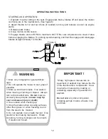
 NOTE: To begin motion the operator must be in the seat and the brake disengaged before
the levers can be moved from the neutral slots or the engine will kill.

By moving the levers an equal amount forward or back the mower will move in a straight line
in that direction.

Movement of the right lever forward will cause the right wheel to rotate in a forward direction.
Movement of the left lever forward will cause the left wheel to rotate in a forward direction. To
stop forward travel pull levers back into the neutral position.

To turn right while moving in a forward direction pull the right lever back towards the neutral
position, this will slow the right wheel and cause the mower to turn in that direction.
To turn left  while moving in forward direction pull the left lever back towards the neutral
position, this will slow the left wheel and cause the mower to turn in that direction.

To zero turn pull one lever back beyond neutral while holding the other slightly ahead of
neutral. NOTE: The direction of the zero turn will be determined by which lever is pulled back
beyond neutral. Thus, left lever back, left turn and opposite for right turn. Use caution when
using this maneuver unit can spin very rapidly if one lever is positioned too much
ahead of the other
.

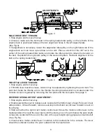
3. Blade engagement switch: Located on the console. Pull up on switch to engage blades,
push down to turn blades off. See page 3

4. Choke control: Located on the console. Pull out on knob to set choke. Use when starting
cold engine do not run choke when engine is warm. See page 3

5. Throttle control: Located on the console. Used to control engine RPM. See page 3

6.  Park brake: Located at the left end of the console. Pull lever back to engage the park
brake, push lever forward to release brake. NOTE: Use tie downs when transporting unit, the
park brake is not enough to hold the unit in place in this situation. See page 3

7.  Key switch: Located on the console. The operator must be in the seat, park brake on,
motion control levers out in the neutral slots and blade switch off before engine will start. See
page 3

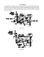
8. Fuel shut off valve: Located on the front of console at the top of the kick plate. The valve
has three positions left tank, right tank and straight down is the off position. See page 3

9.  Pump release valves: Located at the top left corner of the pumps. Used to release the
system so unit may be moved by hand when not running. Tilt the seat up to gain access to the
pumps. Rotate valve towards the front of the unit to release the system using a 5/8 wrench.
NOTE: Only rotate about a 1/4 of a turn to release system.

Summary of Contents for ZKH52222

Page 1: ...portant safety instructions and the other instructions con tained in this manual Lawnmowers and all power equipment can be potentially danger ous if used improperly SAFETY REQUIRES GOOD JUDGEMENT CARE...

Page 2: ...n operating the mower must be of sound mind and body and must not be under the influence of any mind altering substance If you have any questions pertaining to your mower contact your dealer CAUTION 1...

Page 3: ...NSTRUCTIONS 1 Controls 2 Starting and operation MAINTENANCE 1 Engine oil level 2 Pump drive belt compartment 3 Mower blades 4 Safety interlock system 5 Hardware 6 Air cleaner 7 Engine oil 8 Hydraulic...

Page 4: ...fore starting the mower OPERATION 1 Mow only in daylight or good artificial light 2 Do not operate the mower in wet grass if possible 3 Mow up and down slopes Use extreme caution when mowing or turnin...

Page 5: ...of fire keep the mower free of grass leaves and excessive grease or oil 5 Have your mower inspected and serviced each year by an authorized Yazoo Kees dealer 6 Use only authentic Yazoo Kees replaceme...

Page 6: ...position See figure 6 5 Install seat rod to the seat frame with 5 16 hardware Seat rod is located under the seat in the hydraulic pump area Attach the rod to the tab on the seat frame 6 Check engine...

Page 7: ...sition 3 Remove the height adjustment pin and place it in the desired cutting height hole Move deck height lever down onto the pin and mow NOTE anti scalp rollers must be in the proper position for ma...

Page 8: ...e tension may be adjusted by tightening the pivot bolt The pivot bolt holds the throttle arm to the throttle mounting bracket which is located under the console Access is gained by removing the foot p...

Page 9: ...ure to the motion control lever and turn the head of the adjustment bolt in the proper direc tion until the lever is centered in the neutral slot NOTE if properly adjusted the motion control levers wi...

Page 10: ...ke to allow wheels to rotate CAUTION Keep hands feet and clothing away from rotating tires 8 Begin with either side and put the motion control lever into the neutral position Adjust the motion control...

Page 11: ...maneuver unit can spin very rapidly if one lever is positioned too much ahead of the other 3 Blade engagement switch Located on the console Pull up on switch to engage blades push down to turn blades...

Page 12: ...od artificial light 2 Do not operate the mower in wet grass if possible 3 Mow up and down slopes Use caution when mowing or turning on slopes Always turn to the downhill side Do not mow ex cessively s...

Page 13: ...level Check daily with engine cold and on a flat surface Remove the dipstick and wipe clean Reinsert the dipstick all the way Remove the dipstick and check oil level If oil level is low remove oil fil...

Page 14: ...eel motors can occur if the system is ran with an air lock See the specification sheet for the correct kind of oil The factory uses Quaker State Deluxe Motor Oil 20w 50 15 Caster swivel nuts Check at...

Page 15: ...ne Kohler Command V Twin Horsepower 22 or 25 Models CH22S OR CH25S Decks 52 or 61 Cutting Height 1 5 to 5 0 in 1 2 increments 38mm to 127mm in 13mm increments Blades 18 52 deck 21 61 deck Deck Engagem...

Page 16: ...pulls left or right When a problem occurs do not overlook the simple causes For example no fuel or battery disconnected when the engine will not start 1 Tire pressure uneven 2 Motion control linkage a...

Page 17: ...17 WIRING DIAGRAM...

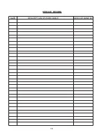
Page 18: ...18 SERVICE RECORD DESCRIPTION OF WORK DONE DATE SERVICE DONE BY...

Page 19: ...es Product warranted hereunder shall be defective or fail to conform with this limited warranty Yazoo Kees shall subject to the provisions hereof pay for or provide labor and materials for the repair...

Page 20: ...FOR ANY INCIDENTAL OR CONSEQUENTIAL DAMAGES RESULTING FROM THE BREACH OF ANY WARRANTY INCLUDING BUT NOT LIMITED TO LIABILITY FOR INCON VENIENCE RENTAL OR PURCHASES OF REPLACEMENT EQUIPMENT OR FOR LOSS...

Page 21: ......

Reviews: