background image

2

1

maINTeNaNCe

49

8065-030

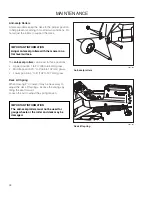
1. Caster bolt
2. Axle spacer

Caster wheel

Use protective glasses when 
cleaning and washing.

Cleaning

Regular cleaning and washing, especially under the 
mower deck, will increase the machine’s life-span. 
Make it a habit to clean the machine directly after use 
(after it is cooled), before the dirt sticks.
Do not spray water on the top of the mower deck. Use 
compressed air to clean the top side of mower deck. 
Regularly clean deck and underside of the deck with 
normal water pressure. Do not use a high pressure 
washer or steam cleaner. Avoid spraying engine and 
electrical components with water.
Do not rinse hot surfaces with cold water. Let unit cool 
before washing.

Caster Wheels

Check every 200 hours. Check that wheels rotate 
freely. 

Removal and Installation

Remove nut and caster bolt.


Pull the wheel out of 

the fork.


Install in reverse order. Tighten caster bolt. 

Torque to 45 ft-lbs (61 Nm), then back nut off ½ turn.
NoTE: Tire should rotate freely but axle spacers 
should not. 
If wheels do not rotate freely take the unit to the dealer 
for service.

Hardware

Check daily. Inspect the entire machine for loose or 
missing hardware.

Summary of Contents for ZPKW5426

Page 1: ...Operator Manual ZPKW5426 966494701 ZPKW6029 966494801 Please read the operator s manual carefully and make sure you understand the instructions before using the machine...

Page 2: ...information contained in these instructions Use only original parts for repairs The use of other parts voids the warranty Do not modify or install non standard equipment to the unit without consent fr...

Page 3: ...Belt 27 Before Starting 27 Starting the Engine 28 Jumper Cables 32 Running 33 Operating on Hills 34 Stopping the Engine 35 Mowing Tips 36 Manual Transport 37 Pump Release Valves 37 MAINTENANCE 38 Batt...

Page 4: ...d mind and body and must not be under the influence of any mind altering substance WARNING Engine exhaust some of its constituents and certain vehicle components contain or emit chemicals known to the...

Page 5: ...ng equipment and ensure that the machine is well anchored DO NOT operate this machine on public roadways Towing If machine is equipped with a tow hitch use extreme caution when towing Never allow chil...

Page 6: ...turing number can be found on the printed plate affixed to the right side in the engine compartment Stated on the plate from the top are The machine s type designation I D The manufacturer s type numb...

Page 7: ...s Do not touch parts marking Only for keep away from the European market discharge deck Battery acid is corrosive explosive and flammable Do not stand here Noise emissions to the surroundings in accor...

Page 8: ...no greater Manual performing any the machine than 10 maintenance or repair work Whole body Severing of fingers Do not open or Careful backing up Careful going exposure to and toes remove safety watch...

Page 9: ...unless absolutely necessary Always look down and behind before and while backing Never direct discharged material toward anyone Avoid discharging material against a wall or obstruction Material may ri...

Page 10: ...ts or counterweights Anyone who operates this machine must first read and understand this Operation Manual Local laws may regulate the age of the user Keep machine free of grass leaves or other debris...

Page 11: ...bstacles Choose a low ground speed so that you will not have to stop while on the slope Do not mow on wet grass Tires may lose traction Avoid starting stopping or turning on a slope If the tires lose...

Page 12: ...sponsible adult other than the operator Be alert and turn machine off if a child enters the area Before and while backing look behind and down for small children Never carry children even with the bla...

Page 13: ...round If this is not possible refuel such equipment with a portable container rather than from a gasoline dispenser nozzle Keep the nozzle in contact with the rim of the fuel tank or container opening...

Page 14: ...gularly to be sure it works properly The machine must not be driven with defective or unmounted protective plates protective cowlings safety switches or other protective devices Do not change the sett...

Page 15: ...ry make repairs before starting Never make adjustments with the engine running The machine is tested and approved only with the equipment originally provided or recommended by the manufacturer Only us...

Page 16: ...ediately Transport The machine is heavy and can cause serious crushing injuries Be extra cautious when it is loaded on or unloaded from a vehicle or trailer Use an approved trailer to transport the ma...

Page 17: ...securely and use park brake If any part of ROPS is damaged the entire ROPS must be replaced Check all bolts including seat belt for correct torque before each use Check ROPS structure for damage befor...

Page 18: ...cking bolt 2 Parking brake 3 Left fuel tank 4 Fuses 5 The power rating of the engines indicated is the average net power output at specified rpm of a typical production engine for the engine model mea...

Page 19: ...control towards the neutral position The rotation of the right wheel is reduced and the machine turns to the right Zero turn can be achieved by moving one control backward behind the neutral position...

Page 20: ...erate unit by driving it at full throttle and 4 the full forward position on both motion control levers Gradually turn in the tracking bolt on the right hand side until the unit noticeably starts drif...

Page 21: ...gine Turn the key clockwise to start the engine 8066 002 Blade switch 8066 004 Ignition switch Parking Brake The parking brake is found on the left of the machine Pull the lever backward to activate t...

Page 22: ...8066 005 Ignition switch accessory CONTROLS 22 8066 010 Ignition switch RUN position Release the key to the RUN position when the engine has started For using accessory turn the key counter clockwise...

Page 23: ...selection pedals 8066 002 Choke control Choke Control The choke control is used for cold starts to provide the engine with a richer fuel mixture For cold starts the control should be pulled out to its...

Page 24: ...in the seat When making adjustments the lever is moved to the left or upward depending on model 8066 006 Lengthways adjustment Fuel Shut Off Valve The fuel shut off valve is located at the left rear...

Page 25: ...Risk for burns if touched Allow engine and exhaust system to cool at least two 2 minutes before refueling WARNING Fill to bottom of filler neck Do not overfill Wipe off any spilled oil or fuel Do not...

Page 26: ...ust be in the seat start engine see Before Starting in the Operation section adjust engine speed to idle disengage parking brake do not engage blades at this time rotate control levers inward As long...

Page 27: ...blades must be depressed The parking brake must be on 2 Roll Bar and Safety Belt Operate the unit with the roll bar in the raised and locked position and use the seat belt There is no rollover protect...

Page 28: ...ully forward Activate the parking brake 3 Disengage the mower blades by depressing the 4 blade switch Move the steering controls outward to the 5 locked outer neutral position 8066 002 Press the contr...

Page 29: ...ve 8 If the engine is cold the choke control should 7 be pulled outward to the choke position 8066 002 Set the choke control 8065 013 Fuel valve in the OPEN position Move the throttle to the middle po...

Page 30: ...RT position When the engine starts immediately release the 10 ignition key back to the run position IMPORTANT INFORMATION Do not run the starter for more than 5 seconds each time If the engine does no...

Page 31: ...choke control in gradually when the 11 engine has started WARNING Engine exhaust and certain vehicle components contain or emit chemicals considered to cause cancer birth defects or other reproductiv...

Page 32: ...the discharged battery away from the fuel tank and battery To remove cables reverse order Remove BLACK cable first from chassis and then from the fully charged battery Remove RED cable last from both...

Page 33: ...ls to the neutral 2 position N The cutting height can be set from 1 5 3 2 5 cm 12 7 cm by setting the cutting height pin into the desired hole Release deck height control by applying equal pressure to...

Page 34: ...regain forward motion Make all turns slowly IMPORTANT INFORMATION Control levers return to neutral when released This may cause the mower to suddenly stop WARNING Do not drive up or down hills with sl...

Page 35: ...ck by depressing the blade switch 8066 009 Disengage the mower deck and move throttle to minimum Raise the mower deck by pressing the foot pedal forward to the transport position When the machine is s...

Page 36: ...The lawn becomes more even and the grass clippings more evenly distributed over the mown area The total time taken is not increased as a higher operating speed can be used without poor mowing results...

Page 37: ...when closing That can damage the valve seat 8065 061 Remove fan cover to access release valves Pump Release Valves Pump release valves are located at the rear of each pump They are used to release th...

Page 38: ...g brake Check the engine s oil level every refueling Check the safety system Check for fuel and oil leakages Check clean the engine s cooling air intake Check the mower deck Check for loose hardware s...

Page 39: ...tely stopped Disconnect the spark plug wire from all spark plugs and place the wire where it cannot come in contact with the plug MAINTENANCE Daily At least once each year Maintenance interval in hour...

Page 40: ...CHARGE 12 4V 75 20 min 35 min 48 min 90 min 12 2V 50 45 min 75 min 95 min 180 min 12 0V 25 65 min 115 min 145 min 280 min 11 8V 0 85 min 150 min 195 min 370 min Charging time depends on battery capac...

Page 41: ...TANT INFORMATION To be able to drive the driver must sit in the seat and release the parking brake before the steering controls can be moved into the neutral position otherwise the engine will stop 80...

Page 42: ...cause an accident Parking Brake Adjustments Using a jack stand raise the rear of the mower 1 up off the ground Make sure the machine is securely supported Remove the rear tire assemblies 2 Release the...

Page 43: ...ee illustration Hold down the safety switch plunger and start 5 the engine Continue to hold the plunger down during the next two steps Keeping the drive levers in the neutral lock 6 position release t...

Page 44: ...Carefully roll the belt over the top of the cutter 4 housing pulleys Remove the belt guide hardware with a 5 wrench and set belt guide aside Remove the belt from around the electric clutch 6 on the en...

Page 45: ...pening in the idler arm shift the arm to create slack in the belt While holding the idler back with the breaker bar wrap the belt around the right pump pulley Replace and secure clutch stop 5 Reinstal...

Page 46: ...lade mounts WARNING Blades are sharp Protect your hands with gloves and or wrap blades with a heavy cloth when handling Blade Replacement Remove blade bolt by turning counterclockwise 1 Install new or...

Page 47: ...measurement Move to the opposite side check that measurement is the same If adjustment is required loosen the locknut and adjust bolt up until both side to side measurements are equal Retain measurem...

Page 48: ...ti scalp rollers must not be used for gauge wheels or the roller and deck may be damaged The anti scalp rollers can be set in three positions Upper position 1 to 2 25 to 63 mm grass Middle position 2...

Page 49: ...e deck with normal water pressure Do not use a high pressure washer or steam cleaner Avoid spraying engine and electrical components with water Do not rinse hot surfaces with cold water Let unit cool...

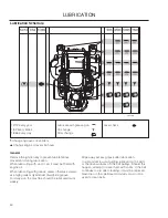
Page 50: ...h grease unless otherwise stated use high grade molybdenum disulphide grease For daily use the machine should be lubricated twice weekly Wipe away excess grease after lubrication It is important to av...

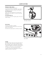
Page 51: ...wheels 8065 033 Deck spindle Deck Spindle Lower the cutting deck completely If a grease gun without rubber hose is used the foot plate must be removed Lubricate with a grease gun 2 3 strokes per spind...

Page 52: ...ove the oil filter from the pump Do not fill above this level Minimum fill level Drain old oil filters of all free flowing oil prior to disposal Place used oil in appropriate containers and dispose of...

Page 53: ...s off the ground then repeated under normal operating conditions Disengage the brake if activated 1 With the bypass valve open and the engine 2 running at fast idle slowly move the directional control...

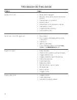
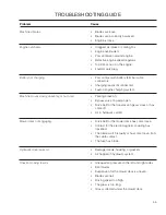
Page 54: ...Poor contacts on the battery terminal cable connections Fuse blown Ignition system faulty Fault in the starter safety circuit See Safety System in the Maintenance Section Engine runs rough Faulty car...

Page 55: ...ransmission gears slack or has come off Air in hydraulic system Mower deck not engaging Drive belt for the mower deck has come loose Contact for the electromagnetic coupling has loosened The blade swi...

Page 56: ...pty the fuel tanks or add a fuel stabilizer Start 4 the engine and allow it to run until the carburetor is drained of fuel or the stabilizer has reached the carburetor Remove the spark plug and pour a...

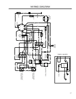
Page 57: ...TIMER SCHEMATIC 57 WIRING DIAGRAM...

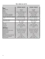
Page 58: ...BE 15 Fuel tanks capacity 12 gallons 45 4 liters 12 gallons 45 4 liters Spark plugs gap NGK BPR4ES 030 0 75 mm NGK BPR4ES 030 0 75 mm Cooling Air cooled Air cooled Air filter Heavy duty canister Heavy...

Page 59: ...sion Hinged Arm Rests Yes Yes Hour Meter Yes Yes Blade Engagement 250 ft lb Ogura 250 ft lb Ogura Deck Construction 7 gauge 7 gauge Productivity 5 acres h 20 234 m2 h 6 acres h 24 280 m2 h Dimension W...

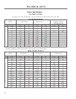
Page 60: ...203 225 305 250 339 370 502 7 8 378 513 591 801 11 8 782 1060 1410 1912 Grade 5 Minimum commercial quality lower quality not recommended Metric Standard Hardware Grade Grade 8 8 Grade 10 9 Grade 12 9...

Page 61: ...s This is also applicable to special requirements for any of the states California emission rules etc Do not remove any of these labels Certificates can also be supplied with the machine at delivery o...

Page 62: ...ty switch for the parking brake Safety switch for the mower deck Safety switch in the seat Safety switch in the steering controls Parking brake functionality and adjustment Driving forward Driving bac...

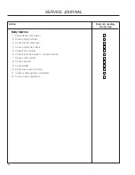
Page 63: ...nge the oil filter 3 Check hydraulic oil level 4 Inspect hydraulic hoses 5 Inspect hydraulic belt 6 Inspect hydraulic filter 7 Check neutral position 8 Check safety system 9 Check seat belt 10 Check R...

Page 64: ...2 Check engine oil level 3 Check the tire pressures 4 Check underside of deck 5 Inspect deck pulleys 6 Check clean the engine s cooling air intake 7 Check safety system 8 Check seat belt 9 Check ROPS...

Page 65: ...he engine oil and filter 3 Check the tire pressures 4 Clean the air filter 5 Grease blade spindles 6 Inspect deck belt and blades 7 Check hydraulic oil level 8 Check safety system 9 Check seat belt 10...

Page 66: ...11 Check engine RPM 12 Clean underside of deck 13 Check blade pitch 14 Grease blade spindles 15 Inspect spindle bearings 16 Inspect deck belt and blades 17 Inspect idler arm bearings 18 Inspect deck i...

Page 67: ...side of deck 13 Check blade pitch 14 Grease blade spindles 15 Inspect spindle bearings 16 Inspect deck belt and blades 17 Inspect idler arm bearings 18 Inspect deck idler pulleys 19 Change hydraulic o...

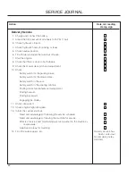
Page 68: ...e the air cleaner s pre filter foam 3 Replace the air filter s paper cartridge 4 Change the engine oil 5 Replace the engine oil filter 6 Check adjust the cutting height 7 Check adjust the parking brak...

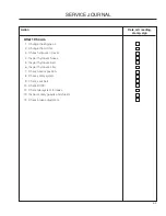
Page 69: ...69 SERVICE JOURNAL Date mtr reading stamp sign Action...

Page 70: ...70 SERVICE JOURNAL Action Date mtr reading stamp sign...

Page 71: ......

Page 72: ...P N 115 263226R1 09 21 09...

Reviews: