Link CX-24 User’s Manual
Version 1.0
Page 14
February 2004
protection. If the mounting point described above provides adequate lightning protection, the Link CX-24
radio will still need a good earth ground to a bare-metal earth ground. Refer to Appendix D for detailed
grounding and lightning protection recommendations.
Cable Routing:
The Link CX-24 DS-3, and/or Ethernet data cables connect associated external
equipment to the Link CX-24 radio. Before installation, procure cable ties and/or standoffs to route and to
create service loops for these cables.
Physical Security:
The Link CX-24 radio is typically mounted high enough to prevent casual tampering.
The Link CX-24 radio is further protected by anti-tampering chassis screws that prevent most casual
attempts to open the chassis.
2.4
Planning Element and Network Management Ethernet Links
2.4.1 Links From the EMS or NMS to the Link CX-24
The Link CX-24 communicates with SNMP-based Element Management Systems and Network
Management Systems over Ethernet communication links. Because the Link CX-24 contains two
independent switched Ethernet ports, one Link CX-24 can be connected directly to an Ethernet switch or
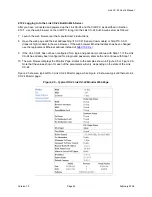
router, and collocated Link CX-24s can be cascaded. Figure 2.2 shows some common arrangements for
the EMS and/or NMS Ethernet links.
The cable run from the Ethernet switch or router to the Link CX-24 must be 100 m (328 ft.) or less, and
can be straight-through or crossover, because the Link CX-24 Ethernet ports automatically detect the
transmit and receive pairs and switch them if necessary. YDI sells 25 m (82 ft.), 50 m (14 ft.), and 100 m
(328 ft.) Ethernet cables with the correct connectors for these links, as described in Section 1.7.6.
Alternatively, when Link CX-24s are to be cascaded as shown in Figure 2.2 (B), YDI sells a 6 m (20 ft.)
Ethernet cable with the correct connectors for the Link CX-24-to-Link CX-24 links, as described in Section
1.7.6. Note that the EMS or NMS must be within eight or fewer Ethernet hops of the Link CX-24 for proper
communications.
2.4.2 Links Between Link CX-24s
As shown in Figure 2.2, the near end Link CX-24 automatically sets up an Ethernet connection to the Link
CX-24 at the far end of each radio system, or link. In Ethernet models, the in-band Ethernet connection
uses the payload data Ethernet link, while in DS-3 models the Ethernet connection is out-of-band, and
does not interfere with the DS-3 payload data. Because the Link CX-24-to-Link CX-24 Ethernet
connection cannot be turned off, make sure you do not connect both ends of the Link CX-24-to-Link CX-
24 to the Ethernet. This will help prevent Ethernet loops and potential data storms.

