Link CX-24 User’s Manual
Version 1.0
Page 26
February 2004
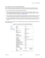
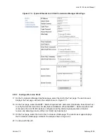
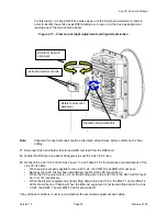
Figure 2.8 – Typical Ethernet Link CX-24 Commission Radio Web Page
Note:
The Link CX-24 is shipped with Tx Attenuation disabled. Make sure this setting remains
unchanged until the rest of the Link CX-24 configuration steps are completed.
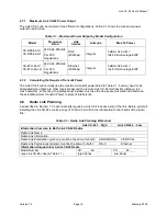
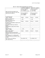
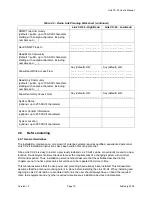
12 Using the data entered on the filled-out copy of the Radio Link Planning Worksheet from Chapter
Three, select the planned configuration choices available on this page, except the final Tx Attenuation
and the Automatic Tx Power Control values. Enable the Tx Attenuation and disable the Automatic Tx
Power Control for now.
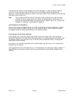
13 Click Submit Changes to upload changes to the Link CX-24.
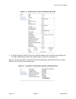
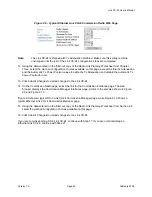
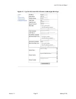
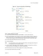
14 On the Commission Radio page, select the link for the Commission Interfaces page. The web
browser displays the Commission Manager Interfaces page, similar to the samples shown in Figure
2.9 and Figure 2.10.
Figure 2.9 shows a typical DS-3 Link CX-24 Commission Manager page, while Figure 2.10 shows a
typical Ethernet Link CX-24 Commission Manager page.
15 Using the data entered on the filled-out copy of the Radio Link Planning Worksheet from Section 2.8,
select the planned configuration choices available on this page.
16 Click Submit Changes to upload changes to the Link CX-24.
If you are commissioning a DS-3 Link CX-24, continue with Step 17. If you are commissioning an
Ethernet Link CX-24, continue with Step 21.

