Link CX-24 User’s Manual
Version 1.0
Page 37
February 2004
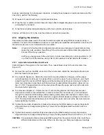
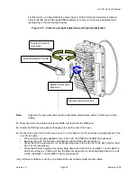
The Link CX-24 is now mounted and aligned. Continue with Section 2.15 for acceptance tests.
2.15 Acceptance
Testing
This section describes the tests used to verify that the Link CX-24 data input circuitry, near-end Link CX-
24 radio, radio link, and far-end Link CX-24 radio are installed properly and operating correctly.
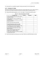
50 Verify that the physical installation is correct. Use Table 2.5 to sign off the individual checks.
Table 2.5 – Physical Installation Checklist
Checklist Item
Verified
Inspector
Date
Is the mounting pipe securely connected to the
mounting structure?
Is the Link CX-24 securely connected to the
mounting pipe?
Is the lightning protection above the Link CX-24
properly grounded?
Is the Link CX-24 properly grounded?
Is the lightning arrestor at the entry to the
equipment enclosure properly grounded?
Is all cabling to the Link CX-24 properly routed
(no sharp bends and properly attached)?
Are all exposed connectors properly sealed
against moisture?
Are all unused connectors capped off or
otherwise sealed against moisture?
Is the antenna polarization correct (as indicated
on the back of the unit)?
51 Verify that the electrical connections are correct. Use Table 2.6 to sign off the individual checks.

