Link CX-24 User’s Manual
Version 1.0
Page iv
February 2004
Appendix D - Grounding and Lightning Protection
58
D-1 Overview ........................................................................................................................................58
D-2 Grounding ......................................................................................................................................58
D-3 Lightning Protection .......................................................................................................................59
Appendix E - Enterprise MIBs and Traps
61
E-1 Enterprise MIBs..............................................................................................................................61
E-2 Enterprise Traps.............................................................................................................................79
Bibliography 80
FIGURES
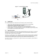
Figure 1.1 – Link CX-24 Power Supply ..................................................................................................2
Figure 1.2 – Typical Radio Link Configurations......................................................................................3
Figure 1.3 – Link CX-24 Star Network....................................................................................................3
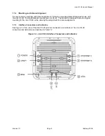
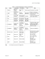
Figure 1.4 – Link CX-24 Interface Connectors and Indicators ...............................................................5
Figure 1.5 – Integral Antenna and Link CX-24 Radio.............................................................................7
Figure 2.1 – Preventing Multi-path Fading from Ground-Level Surfaces.............................................13
Figure 2.2 – Typical EMS/NMS Ethernet Connections ........................................................................15
Figure 2.3 – Link CX-24 Orderable Parts .............................................................................................20
Figure 2.4a – Link CX-24 Configuration Setup.....................................................................................22
Figure 2.4b – Link CX-24 Positive-Ground Power Connections ..........................................................23
Figure 2.4c – Link CX-24 Negative-Ground Power Connections .........................................................23
Figure 2.5 – Typical DS-3 Link CX-24 Monitor Web Page ...................................................................24
Figure 2.6 – Typical Ethernet Link CX-24 Monitor Web Page..............................................................25
Figure 2.7 – Typical DS-3 Link CX-24 Commission Radio Web Page.................................................25
Figure 2.8 – Typical Ethernet Link CX-24 Commission Radio Web Page ...........................................26
Figure 2.9 – Typical DS-3 Link CX-24 Commission Manager Web Page ............................................27
Figure 2.10 – Typical Ethernet Link CX-24 Commission Manager Web Page ....................................28
Figure 2.11 – Typical Link CX-24 DS-3 Test Web Page ......................................................................29
Figure 2.12 – Link CX-24 Mounting Components ................................................................................30


