background image

www.ydlidar.com Copyright 2015-2019 EAI

11

/

12

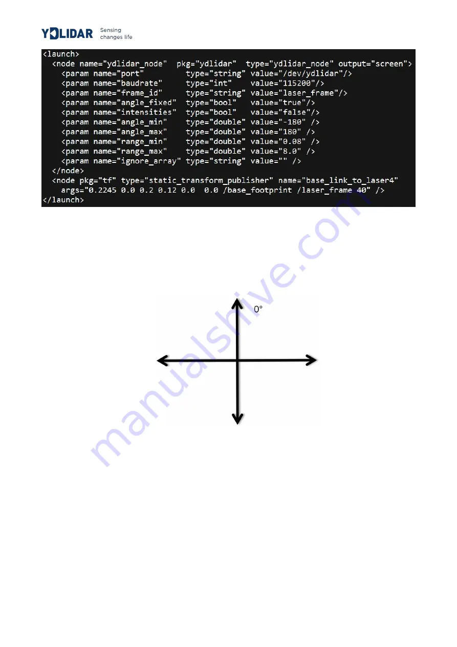
FIG 14 LIDAR.LAUNCH

FILE

2

The X2 lidar coordinates follow the right-hand rule within ROS, with an angle range

of [-180, 180]. "angle_min" is the start angle, and "angle_max" is the end angle.
The specific scope needs to be modified according to actual use.

90°

- 90°

180°/-180°

FIG15 YDLIDAR X2 COORDINATES DEFINITION

PRECAUTIONS FOR USE

Temperature

When the working environment temperature of X2 is too high or too low, it will affect the
accuracy of the distance measuring system. It may also damage the structure of the
scanning system and reduce the life of the X2 lidar. Avoid use in high temperature (>40
degrees Celsius) and low temperature (<0 degrees Celsius) conditions.

Summary of Contents for X2

Page 1: ...https www facebook com ydlidar YDLIDAR X2 USER MANUAL DOC 01 13 000102...

Page 2: ...tware 4 Start scanning 6 System settings 6 Save data 7 Angle calibration 7 Firmware upgrade 8 LINUX ROS OPERATION 9 Device connection 9 ROS Driver Installation 9 RVIZ installation 9 RVIZ Check the sca...

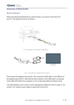
Page 3: ...FIG 2 YDLIDAR X2 CONNECTION STEP 2 First connect the adapter board and X2 then connect the USB cable to the USB port of the adapter board and PC Note that the Micro interface of the USB cable is conn...

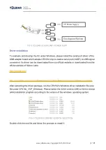
Page 4: ...ded from our official website or downloaded from the official website of Silicon Labs http ydlidar com http cn silabs com products development tools software usb to uart bridge vcp drivers After extra...

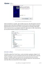
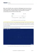
Page 5: ...essfully installed The figure below is COM3 Note that the port should be checked if X2 and PC are interconnected FIG 6 YDLIDAR X2 DRIVE INSTALLATION Evaluation software YDLIDAR provides Point Cloud Vi...

Page 6: ...nding serial port number and model number FIG 7 YDLIDAR X2 EVALUATION SOFTWARE Note The Lidar does not turn on the heartbeat function by default This function needs to send the scan command continuous...

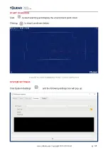
Page 7: ...2 START SCANNING Click to start scanning and display the environment point cloud Clicking to stop it as shown below FIGURE 9 LIDAR SCANNING POINT CLOUD DISPLAY10 SYSTEM SETTINGS Click System Settings...

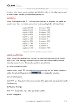
Page 8: ...TION During the mechanical assembly of the Lidar the user may have a deviation in the zero angle In this case the angle calibration function of the client can be used to calibrate according to actual...

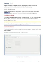
Page 9: ...ed FIRMWARE UPGRADE Click System Settings and select Firmware as shown in Figure 10 Click to get the latest firmware When there is a new version the user can click on the control to perform a firmware...

Page 10: ...vice Connection under Window ROS Driver Installation Before doing the following make sure that the Kinetic version ROS environment is installed correctly 1 Use the command to create the ydlidar_ws wor...

Page 11: ...ngle problem The scanning data seen by running the launch file is displayed by default with 360 degree data To modify the display range you need to modify the configuration parameters in the launch fi...

Page 12: ...s to be modified according to actual use 0 90 90 180 180 FIG15 YDLIDAR X2 COORDINATES DEFINITION PRECAUTIONS FOR USE Temperature When the working environment temperature of X2 is too high or too low i...

Page 13: ...or chip thus invalidating the distance measurement Please note that the X2 standard version is subject to interference in outdoor strong sunlight reflection environments Power demand During the develo...

Reviews: