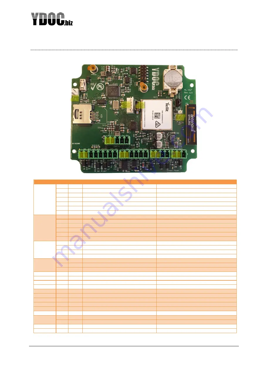
ML-x17 DATA LOGGER MANUAL
Manufacturers of low power instruments
page 124
5
Pin configuration
Connector
Pin
Name
Description
X1
1
A1
0..20mA, input 1
Positive terminal analog input 1
2
A2
0..20mA, input 2
Positive terminal analog input 2
3
A3
0..10V, input 3
Positive terminal analog input 3
4
A4
0..10V, input 4
Positive terminal analog input 4
5,6
GNDs
GND
Ground
7
PM
0..100% (0..3300mV), input 5
Positive terminal potentiometer/analog input 5
8
PR
Reference voltage terminal
3.30V potentiometer reference terminal
X2
1
Tx
RS232 TX
Transmit line RS232
2
Rx
RS232 RX
Receive line RS232
3
A+
RS485 A
+RS485 positive terminal
4
B-
RS485 B
-RS485 negative terminal
5
SDI
SDI-12 (0..5V)
Terminal to connect SDI-12 sensors
6
GND
GND
Ground
X3
1
D1
Digital input 1 (0..5V)
Positive terminal digital input 1 or wake-up line
2
D2
Digital input 2 (0..5V)
Positive terminal digital input 2
3
D3
Digital input 3 (0..5V)
Positive terminal digital input 3
4
GND
GND
Ground
X4
1
12V
100 or 200mA (ML-x17) sensor power
Terminal to supply power to sensors
2
AO
Alarm output
Open collector (max 100mA sink current)
3
GND
GND
Ground
X5
1
5V
600mA or 800mA (ML-x17) acc. power
To power an accessory (e.g. TFT, CAM, GPS)
2,3
GNDs
GND
Ground
4
Tx
RS232 TX
Transmit line RS232 to accessory RX
5
Rx
RS232 RX
Receive line RS232 from accessory TX
X6
1
GND
USB shield GND
2
GND
USB GND
3
USB_data_P
Positive USB data signal
4
USB_data_N
Negative USB data signal
5
USB_VBUS
USB bus 5 Volts input
X7
External antenna connector
U.FL connector for external antenna
J1
1
+VBAT (3.6V DC)
Positive terminal for power source
2
-VBAT (3.6V DC)
Negative terminal for power source
J2
Internal USB connector
USB connector for local configuration
X1
X2
X3
X4
X5
X6
X7
J1
J2


