ML-x17 DATA LOGGER MANUAL
Manufacturers of low power instruments
page 39
4.11 Analog inputs
4.11.1 Sensor power switch
Here, you can specify if you want to power the sensor from the 12V sensor power switch. You also need
to define a ‘Warm up’-time, which is the time needed by the sensor to produce a valid and stable value
after applying power. More on the power switch see chapter:
Power Switch_Power_Switch
4.11.2 Sample interval
Interval on which the sensor is measured. Normally set to data log interval.
4.11.3 Port mode
The user can select the mode of the analog input (0..20 mA or 4..20 mA or Volts (volt port))
4.11.4 Parameter settings
See chapter:
Parameters_Parameters
4.11.5 Parameter value at (min & max range)
Here, the user can specify the mapping between the physical values to be measured and the sensor
output signal. Please specify the theoretical expected physical value at the minimum output signal of the
sensor and the expected physical value at the maximum output signal (e.g. 4mA equals a level of 0m of
water and 20mA equals to 10m. A linear interpolation will be performed on all values in between.
4.11.6 Determine linear conversion function (2 calibration
points)
This is an automated function to help the user to set the right conversion function into the data logger.
This feature will determine the same function as described above, but will use a physical readings instead
of a manually entered figures. The user will be prompted to measure and enter physical values at 2
calibration points (e.g. 2 different sensor heights in a water column). This feature is convenient while
performing a field calibration and no factory calibration data of the sensor is available.
4.11.7 Determine linear offset only (1 calibration point)
This features is an automated calibration function for the offset only, make sure you have first specified
the theoretic correct range (see above: Parameter value at). The user will be prompted to measure and
enter the physical value at 1 calibration point. This procedure is a/o convenient when you have installed a
level sensor, but you
don’t know it’s exact well depth.
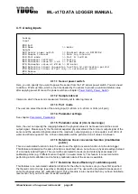
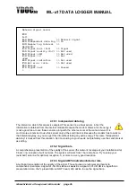
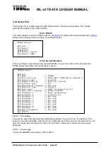
Analog
input
[0] Exit
[1] Name >> Water
height
[2] Sensor power switch >> Enabled; Warm up 00:00:02
[3] Sample interval >> Data log interval
[4] Port mode >> Port 1; 4-20 mA
[5] Parameter settings >> Analog
[6] Parameter value at 4 mA >> 0 meter
[7] Parameter value at 20 mA >> 10 meter
[8] Determine linear conversion function (2 calibration points)
[9] Determine linear offset only (1 calibration point)
[R] Remove
[T] Test measurement
>


