ML-x17 DATA LOGGER MANUAL
Manufacturers of low power instruments
page 42
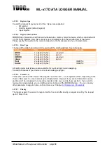
4.12.8 Log each
counter change
This is only possible with low frequency sensors. The event is logged and a timestamp is added. I.e. if
you like to count the customers, visiting your store, and you like to make a nice statistical graph, this
feature is convenient (you can see busy hours, slow hours etc.).
4.12.9 Counter
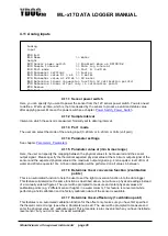
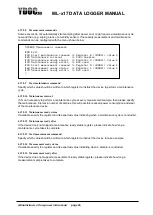
This is the parameter, connected to the digital input. It behaves like a normal parameter (see
Parameters
)
Note that the counter is not directly related to the amount of pulses at the input, the value is first scaled by
the “pulses per unit” or “units per pulse” factor
4.12.10
Quantity
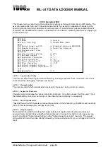
The Quantity is the number of units occurred during the log interval. So, if you add up all Quantities, the
value is the same as the counter. This is convenient with i.e. rain measurements. The counter gives you a
total of all precipitation since installation (or last automatic reset), and the quantity gives you the value per
log interval.
4.12.11
Mean-, Max- and Min Rate
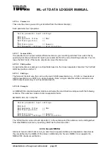
This is the speed of increase of the counter value. When e.g. a water meter is connected. The counter
contains the total pumped volume, and the rate contains the flow of the water. The unit is: units/h (in case
of the water meter l/h).
4.12.12
Activity period
This can be used to detect the length of e.g. a period of water flow, the time is measured from the first
pulse till pulsing stops for a certain amount of time (end detection time). The start time will be logged with
a 0 value and the end time (time of last pulse in the period) will be logged with the time past since the
start time. Regular data logs in between will be logged with a value representing the time past between
the data log timestamp and the start time.
4.13 Digital inputs - Alarm trigger
This feature uses the same electrical input as the previous (digital input: pulse counter), but it handles the
signal differently. When the input is configured as an alarm input, instead of a pulse input, it has another
menu and the purpose of the measurements is different. The difference between the pulse measurement
and the alarming mode, is that with pulse measurement the change of the input signal is expected, and
very often frequently, while in
the alarming mode, a change in input signal is an exception. That’s why you
don’t find functions like min, max, average. The Digital Alarm itself is not an Data Alarm, but puts the
logger into alarming mode (using alarm intervals if applicable), and starts a direct measurement of all
sensors trying for instance to catch data alarms, and the driver also directly logs it’s changing state. If you
also have put on direct data output on alarm (general settings), the logger will also start the output drivers
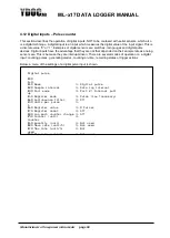
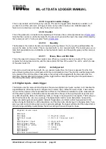
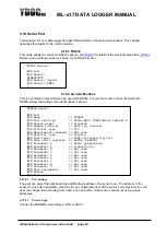
(at both rising and falling levels). Below the menu-settings of an alarm-input is shown.
Digital alarm input
[0] Exit
[1] Name >> Digital alarm
[2] Port mode >> Port 2; Internal pull
up
[3] Digital input >> High active
[4] Trigger delay >> 00:00:01
[5] Register value >> 13 Alarms
[6] Alarm >> Alarm
[7] Counter >> Counter
[R] Remove
[T] Test measurement
>


