ML-x17 DATA LOGGER MANUAL
Manufacturers of low power instruments
page 47
E.g. a northern wind flapping between 340 and 10 degrees will result in an average northern wind of 355
instead of a faulty 175 degrees southern wind.
Some values (like Noise) are expressed in dB and as dB is a logarithmic value the individual values have
to be linearized first before averaging (e.g. the average of 10dB +20dB is not 2 but 17.4dB).
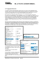
Choose an aggregation period, a commonly used wind speed aggregation period is 10 minutes. Each
aggregation buffer can hold max 600 values, so values for a 10 minute aggregation can be sampled with
1Hz. If you want a 20 min aggregation sampled with 1Hz, then 2 second averages will be used.
4.17.1.1
Average, minimum, maximum, gust, standard deviation & change
Choose which aggregation results you want to record, being average, minimum, maximum gust, standard
deviation, gust and change. A gust is the highest 3 sample average occurred in an aggregation period.
Percentage of change is the change in percentage relative the oldest value in the aggregation period.
Rate of Change is the difference between the youngest and oldest value over the aggregation period and
scaled to a rate in unit per hour.
4.17.1.2
Percentiles
It
’s also possible to define up to 3 different percentiles in ascending or descending order. E.g. to
determine the background noise in a certain area you can sample the noise in dBA and take the 95%
percentile of all sample noise values in descending order. The value returned (LA95) will be the noise
level not exceeded by 95% of the values. The noise peak load (LA10) can be determined by taking the
10% percentile in descending order. A 50% percentile will give the median.
4.18 Calculation Channels
Besides the different Physical channels,
the data logger contains, it also has a number of “calculation
channels”. These are very powerful, virtual channels. i.e. they are not real physical input channels, but
virtual channels to hold i.e. an in between result, for a complex calculation. It allows the user to perform
complex calculations in order to transform the electrical signal from the input to a real-life value. It enables
the user the connection of a very wide range of sensors, including non-linear ones. All kind of
mathematical functions can be used inside a calculated channel. The section covers how to use
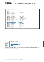
calculated channels and gives you a real-life example. Calculated channels are found in the configuration
setup (below)


