ML-x17 DATA LOGGER MANUAL
Manufacturers of low power instruments
page 68
user has to work with the coordinates, coming from the GPS, and they are not comprehensive at all. Also,
very often, the user has a good idea about the maximum allowable drift of the buoy, but NOT yet the
starting location of it.
4.20.5.4
GPS time update
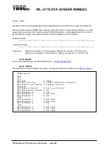
If the data logger cannot use NTP to stay in sync with UTC time, you can use the timestamp transmitted
by the satellites to sync with.
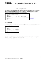
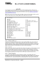
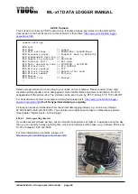
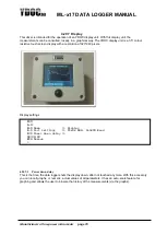
4.20.5.4.1 Calculate alarm limits on deployment
This feature helps the user to set up a region which will be guarded by the data logger. This region can be
setup at the office, far away from the installation site. The region is setup by defining the size of a
rectangular, in which the buoy is supposed to operate. The buoy can drift in this box, without causing an
alarm. The parameters of this box are:
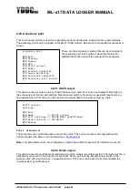
4.20.5.4.2 Latitude/Longitude hi/lo alarm drift
Both limits represent (geographical) seconds, and likewise, a box is created with the size of 2 times the
latitude hi/lo alarm drift by 2 times longitude hi/lo alarm drift. So, this box has a user defined size, but is
unrelated to the position of deployment. At deployment, these values are automatically related to the
(starting) position of the system. It automatically calculates the alarm limits for the parameters latitude and
longitude.
Thanks to this, the user can define a “box of allowed movement” at the office, and during
deployment, the absolute alarm limits for latitude and longitude are calculated.
Also, the user can define a second, bigger, box, which corresponds with the hi/hi limits of the data logger.
So, a second level of alarming can be defined.
4.20.5.5
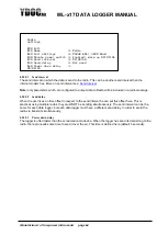
Satellites
The amount of satellites, used in the calculation of the position. This parameter is retrieved from the
standard NMEA string.
4.20.5.6
Latitude / Longitude / Altitude
Notation of the position, in the WSG84 system,
4.20.5.7
GPS Quality
Quality of the measurement. More info on this is found in the manual of your GPS.

