USER MANUAL
TYPE ML-2012/13
Manufacturers of low power instruments
page 34
5
Pin configuration
5.1 ML-2012
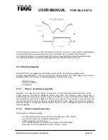
The arrows are pointing to the #1 pin
Connector
Pin#
Name
Description
X1
1
RS485 A
+RS485 positive terminal
2
RS485 B
-RS485 negative terminal
3
GND
Ground
X2
1
GND
Ground
2
RS232 TX1
Transmit line RS232 port 1
3
RS232 RX1
Receive line RS232 port 1
4
RS232 TX2
Transmit line RS232 port 2
5
RS242 RX2
Receive line RS232 port 2
X3
1
0..20mA input 1
Positive terminal analog input 1
2
0..20mA input 2
Positive terminal analog input 2
3
0..20mA input 3
Positive terminal analog input 3
4
0..20mA input 4
Positive terminal analog input 4
5-8
GND
Ground
X4
1
SDI-12 (0..5V)
Terminal to connect SDI-12 sensors
2
Switched power output (12V@100mA)
Terminal to supply power to sensors/transponders
3
n.c.
n.c.
4
GND
Ground
X5
1
+coil
input 4
(waveform ~50mV)
Positive terminal digital
input 4
2
-coil
input 4
(waveform ~50mV)
Negative terminal digital
input 4
3
Digital input 1 (0..5V)
Positive terminal digital input 1
4
Digital input 2 (0..5V)
Positive terminal digital input 2
5
Digital input 3 (0..5V)
Positive terminal digital input 3
5,7
GND
Ground
X7
ANT
U.FL connector for GSM antenna
X8
USB
USB connector for local configuration
J1
1
+VBAT (0.8 .. 5V DC)
Positive terminal for power source
2
-VBAT (0.8 .. 5V DC)
Negative terminal for power source


