background image


USER MANUAL 

TYPE ML-2012/13


Manufacturers of low power instruments 


page 35


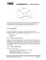
5.2  ML-2013 


The arrows are pointing to the #1 pin 


Connector 

Pin# 

Name 

Description 

X1 

RS485 A 

+RS485 positive terminal 

RS485 B 

-RS485 negative terminal 

GND 

Ground 

X2 

GND 

Ground 

RS232 TX1 

Transmit line RS232 port 1 

RS232 RX1 

Receive line RS232 port 1 

RS232 TX2 

Transmit line RS232 port 2 

RS242 RX2 

Receive line RS232 port 2 

X3 

0..20mA input 1 

Positive terminal analog input 1  

0..20mA input 2 

Positive terminal analog input 2 

0..20mA input 3 

Positive terminal analog input 3 

0..20mA input 4 

Positive terminal analog input 4 

+diff. input 5 (0..2000mV) 

Positive terminal analog input 5 

-diff. input 5 (0..2000mV) 

Negative terminal analog input 5 

+diff. input 6 (0..80mV) 

Positive terminal analog input 6 

-diff. input 6 (0..80mV) 

Negative terminal analog input 6 

X4 

Switched module power output (5V) 

Terminal to switch on external modules (a/o display) 

SDI-12 (0..5V) 

Terminal to connect SDI-12 sensors 

Switched power output (12V@100mA) 

Terminal to supply power to sensors/transponders 

Switched stable excitation (5V@80mA) 

Terminal to supply a stable power to bridge sensors 

5,6 

GND 

Ground 

X5 

+coil 

input 4

 (waveform ~50mV) 

Positive terminal digital 

input 4


-coil 

input 4

 (waveform ~50mV) 

Negative terminal digital 

input 4


Digital input 1 (0..5V) 

Positive terminal digital input 1 


Digital input 2 (0..5V) 

Positive terminal digital input 2 


Digital input 3 (0..5V) 

Positive terminal digital input 3 


5,7 

GND 

Ground 

X7 


ANT 

U.FL connector for GSM antenna  

X8 


USB 

USB connector for local configuration 

J1 

+VBAT (0.8 .. 5V DC) 

Positive terminal for power source 

-VBAT (0.8 .. 5V DC) 

Negative terminal for power source 

Summary of Contents for ML-2012

Page 1: ...USER MANUAL TYPE ML 2012 13 Manufacturers of low power instruments page 1 Type ML 2012 13 Low power GPRS data logger Title User Manual ML 2012 13 Date 30 Oct 2014 Version 1 4...

Page 2: ...12 13 data logger prepares you to install it and tells you how to put it into operation The Chapter Operating Basics covers basic principles of operation of the data logger The operating interface men...

Page 3: ...4 6 Analog Differential Inputs ML 2013 only 20 4 6 1 Differential input ports theory of operation 20 4 6 2 Common mode noise rejection 20 4 6 3 Using Load Cells With the ML 2013 20 4 6 4 Bridge of Whe...

Page 4: ...tion Battery Life 33 5 Pin configuration 34 5 1 ML 2012 34 5 2 ML 2013 35 5 3 Pin Description 36 5 3 1 Analog Inputs 36 Analog Input 1 to 4 36 Analog Input 5 to 8 ML 2013 only 36 5 3 2 RS 485 A B 36 5...

Page 5: ...be used to connect pyranometers or in combination with a stable excitation voltage to connect Wheatstone resistive bridge sensors like load cells The data logger is provided with generic serial port d...

Page 6: ...the logger to an external VDC source ML 2013 AC As ML 2013 but with 85 265V AC adapter integrated in cover To connect the logger to an AC power grid ML 2012 13 PCB As ML 2012 13 but without enclosure...

Page 7: ...de PA66 GF20 with in between a silicon gasket The ML 2013 can be used outdoors 1 Analog inputs 2 RS232 connector 3 Excitation DC DC convertor 4 Digital inputs 5 SDI 12 power switch and Excitation conn...

Page 8: ...he menu the configuration and network settings must also mach to those supplied by the SIM card provider The pin code of the SIM card must be removed prior to insertion in the data logger To prevent p...

Page 9: ...on both devices ESD discharges could cause invisible damage This endangers long term stability and proper operation 2 3 Power on for the First time In the factory the data logger is programmed with th...

Page 10: ...of the firmware NOT the wiring For wiring information see the reference Example Let s Configure a ML 2012 13 for operation with the following Analog pressure transmitter 4 20mA CT2X conductivity tempe...

Page 11: ...Next type 7 for Analog sensors Choose 1 for Port 1 mA and the next screen will appear General settings 0 Exit 1 System Name YDOC 2 Data logging interval Normal 00 01 00 Alarm Not Used 3 Direct Data ou...

Page 12: ...urement at 1m water level and a measurement at 2m water level while the sensors range is 0 10m 6 If necessary option 9 can be used to perform an offset correction by measuring a single calibration poi...

Page 13: ...e interval of digital sensors too short 1 second is possible but probably not sec Just to be sure we choose 10 sec Consult the manual of your digital sensor and check the response time The sample inte...

Page 14: ...ddress So make sure this address is valid Now perform an Email test and check if it is working right It is strongly recommended to include some internal sensors in the configuration because of the mon...

Page 15: ...V Ctrl D The result should be like this Internal sensors 0 Exit 1 Name Internal 2 Sample interval Normal 00 00 01 Alarm Not Used 3 Battery Capacity mAh 17000 4 Battery replaced Yes 5 Rest Capacity Res...

Page 16: ...is in the active state When the data logger is in sleep mode the tasks triggered by the sample interval will NOT execute 4 1 2 Data logging interval This interval determines when a data value obtaine...

Page 17: ...user can evaluate these values every 5 seconds 4 2 SDI 12 The ML 2012 13 is provided with an SDI 12 port This port is connected to port 2 and is shared with the normal RS232 operation This means that...

Page 18: ...ast character it switches to RX mode immediately without the delay Therefore no replies are missing Your ML 2012 13 has a true SDI 12 port For more information on the SDI 12 protocol see www sdi 12 or...

Page 19: ...as a master and retrieves the information from the slaves Only one slave can respond to the requests of the master at a time To set up your RS485 sensor for use with the ML 2012 13 make sure that the...

Page 20: ...s are very sensitive and particularly suitable for measuring signals from load cells 4 6 1 Differential input ports theory of operation Differential inputs are very convenient for measuring differenti...

Page 21: ...table reverence Voltage often called Excitation Voltage The ML2013 has an Excitation output for this purpose 4 6 5 Excitation Output The ML 2013 has an Excitation output for powering load cells or oth...

Page 22: ...is adjusted For input 5 this is very accurate it will be 0 05 For an application that requires an even higher accuracy the user can and should do a user overall calibration 4 6 9 Overall Calibration...

Page 23: ...r systems or NPN outputs 4 7 2 Pull down type The pull up type of input means that there is an internal resistor mounted between the input and the ground So when NO signal is connected the input will...

Page 24: ...his alarm level is reached when the data logger encounters a value which is higher than the high high Limit this is the 2nd and most urgent state of alarming This type of alarming is used for very rar...

Page 25: ...ort 4 10 1 When to use Firmware upgrades Normally a user never uses this feature as long as he is satisfied with the performance of the system In time however the need for additional features may aris...

Page 26: ...f INW CT2X sensors This sensor measures temperature and conductivity So each sensor uses two parameters Also he likes to send the data via FTP and he enables the following internal sensors Rest Capaci...

Page 27: ...card adaptor or can be downloaded from the card by using the menu option Data download We recommend not removing the SD card from the logger 4 11 1 Inserting an SD card At the factory the SD card is a...

Page 28: ...So the D record consists of a D character followed by a timestamp and after that one or more series of parameter code and parameter name So the D record consists of these elements 1 D 2 Parameter Cod...

Page 29: ...m Message A short and comprehensive message to explain the type of problem encountered Additional System Message Some more information on the exception Example S records 4 12 3 Data Modifiers Normally...

Page 30: ...ming a lot of power so try to minimize this Consult the manual of the sensor for warm up times A warm up time of 5 minutes is possible and can be used in rare situations but the battery life will be s...

Page 31: ...other measurement For safety reasons a user can include some internal measurements in the configuration to allow monitoring of the performance of the system Example configuration Rain Measurement Here...

Page 32: ...Quantity Quantity is the difference between the actual counter value and the previous counter value So when your data log interval is set to 10 minutes this parameter shows you the amount of pulses p...

Page 33: ...the data logger this power monitor keeps track of the power consumption of the device When the device is going into sleep mode a fixed value is used to calculate the power consumption Both are calcula...

Page 34: ...ve terminal analog input 3 4 0 20mA input 4 Positive terminal analog input 4 5 8 GND Ground X4 1 SDI 12 0 5V Terminal to connect SDI 12 sensors 2 Switched power output 12V 100mA Terminal to supply pow...

Page 35: ...input 6 0 80mV Positive terminal analog input 6 8 diff input 6 0 80mV Negative terminal analog input 6 X4 1 Switched module power output 5V Terminal to switch on external modules a o display 2 SDI 12...

Page 36: ...5 3 3 Power Switch This is an output to drive one or more sensors It holds a level of 12 Volts and is capable of driving up to 200 mA 5 3 4 VBAT This is the main power supply input for the board The...

Page 37: ...re the antenna is in vertical position as the GSM and GPRS radio signals are vertically polarize the antenna should be vertical positioned for maximum performance Do not place the antenna near metal s...

Page 38: ...fe stability see spec sheet Also when operating in a harsh environment the need for a recalibration can be applicable YDOC can perform overall calibrations any time you like 6 3 XRAY In the uncommon e...

Page 39: ...disposed Regulations for disposal of batteries may be different Remove the batteries and dispose them in accordance to the local regulations for batteries 9 Transport and Storage The following requir...

Page 40: ...solution 12 bits Input type 0 20 mA Channel 1 to 4 Number of Differential Channels 2 ML 2013 only Resolution 16 bits Input type Voltage 0 2000 mV 8 different ranges Smallest detectable step 1 uV Memor...

Page 41: ...USER MANUAL TYPE ML 2012 13 Manufacturers of low power instruments page 41 11 EU Declaration of Conformity 11 1 ML 2012...

Page 42: ...USER MANUAL TYPE ML 2012 13 Manufacturers of low power instruments page 42 11 2 ML 2013...

Page 43: ...RS232 485 SDI 12 Generic SDI 12 NMEA GGA Generic RS232 NMEA DBT Generic RS232 NMEA HDG Generic RS232 NMEA MWV Generic RS232 AWAC Current Nortek RS232 AWAC Wave Nortek RS232 Thalimedes OTT RS232 SDI12...

Page 44: ...y wrong it must be adjusted If it is totally out of date it designates a RTC problem There should be NO errors on this startup If there are errors contact your local YDOC dealer A screen dump of the s...

Page 45: ...end us an email with your comments Thank you for your assistance Manual Name ML 2012 13__________________________________________________________ Revision Number 1 0___________________________________...

Reviews: