7
6
EN
1.b
1.e
2.
5.b
5.c
5.d
1.c
1.a
1.d
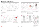
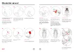
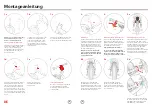
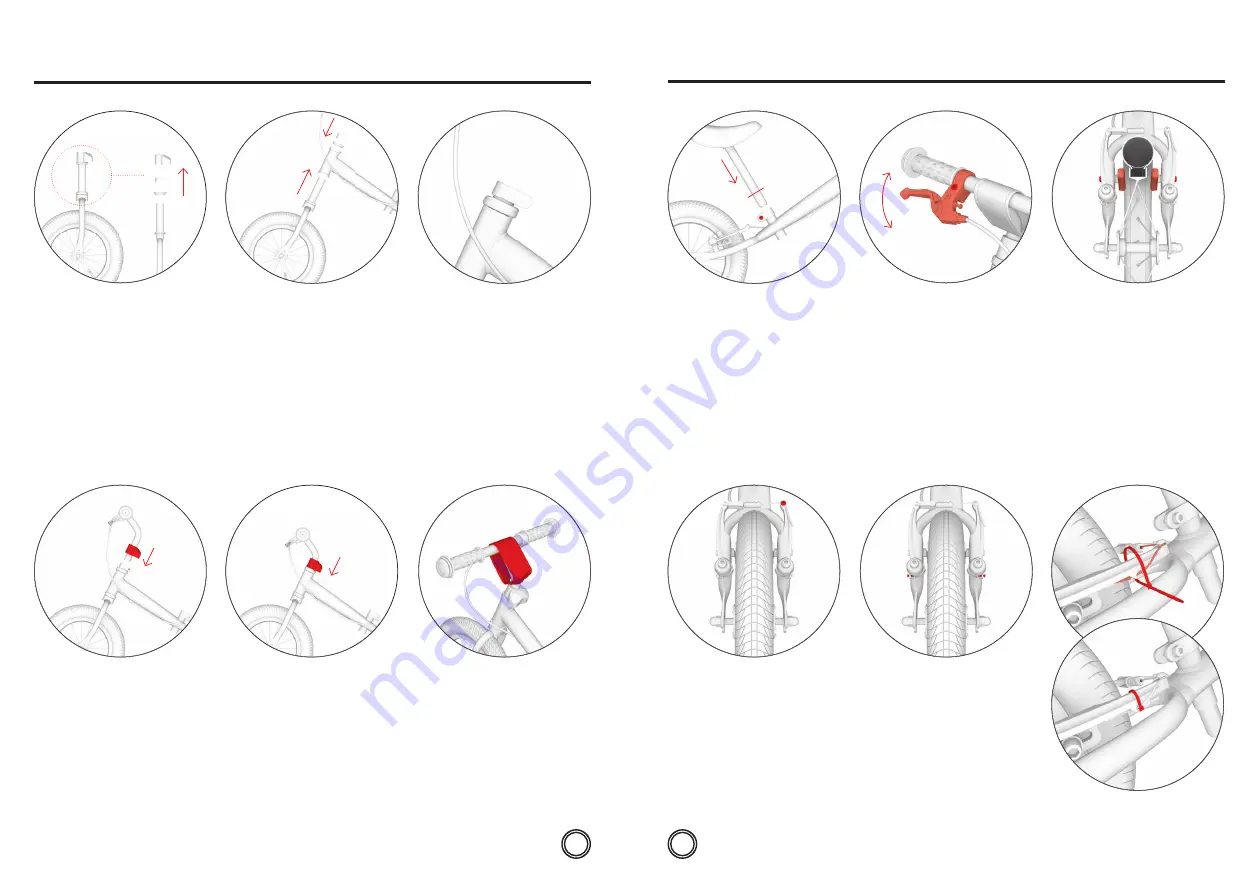
Before assembly, remove the plastic
covers from both front and rear wheel
axis.
Handlebar and front fork installation:
Remove the sleeve cover, the sleeve
itself and upper the headset ring
from the front fork. At installation,
the headset composition must be as
on the picture.
Put the sleeve cover (
1
) on the handlebar
tube and place it into the fork tube (
2
).
Adjust the heigh as desired (do not
exceed the maximum mark) and tighten
the screw on the sleeve (
3
).
In the end, place the protective cover
over the sleeve.
Protective pad installation:
Place the soft protective pad from
washable nylon over the handlebar
stem.
Check that the pads make enough
space (1–2 mm) after releasing the brake
levers. The distance can be adjusted by
tightening or loosening the brake cable
at the anchor screw (
2
).
In case the brake pad is touching
the wheel when turning, symmetrically
adjust the distance of brake arms by
the tightening screws (
3
).
Insert the front fork into the main frame
tube (
1
) so that the bending of the fork
faces forward. Place the upper headset
ring (
2
) and the sleeve (
3
) back on the
front fork.
Place the sleeve screw exactly
on the cut-out of the fork tube
as on the picture.
3.
4.
5.a
Seat installation:
Put the seat tube into the frame (
1
) of
the running bike, adjust the desired
height (do not exceed the maximum
mark) and tighten the sleeve screw (
2
).
Then inflate the tires according to
the values on their side (ideally
between 1,5 and 2 bars).
Adjustment of brake levers: (OneToo)
Incline the brake levers correctly by
loosening the screw on the sleeve (
1
).
The right inclination:
Let the child sit on the running bike,
hold the handles and stretch out your
fingers in a way that his/her arm and
the fingers form a single straight line.
This should be the position of the brake
lever.
Adjustment of brake: (OneToo)
When braking, check that the brake
pads fit tightly on the rim sides. Their
position can be adjusted via the
screws (
1
). The pads shall not touch
the tires.
Fasten the end of the brake cable in
the lock and secure with the cable tie,
then trim the tie.
1
1
2
2
3
10 Nm
3
Assembly Instructions
1
1
1
2
2
6 Nm
2
Max
1
1
5 Nm
3
3


