


Yellow Diving heating system manual
3
General informations
Yellow Diving heating system is intended to be used exclusively for dry-suit and
dry-gloves diving to maximum depth of 150m (450fsw). The system consists of
dry suit connector, battery pack canister, with battery capacity depending on
chosen model and a thermo-active heating vest and heating gloves.
Dry suit connectors
The are four different configurations of Yellow Diving heating system, depending
on dry suit connector used:
•
THERMOV
– integrated inlet dry-suit valve and heating connector.
Suitable for replacing original Apeks and Si-Tech inlet valves.
•
VALVEAP
– dry suit connector mounted under original Apeks inlet valve
•
VALVESI
– dry suit connector mounted under original Si-Tech inlet valve
•
THROU
– connector mounted in a hole punctured in dry suit layer.
Connector mount
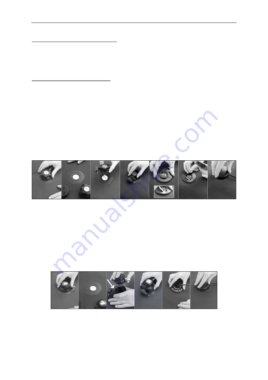
THERMOV
– Follow these steps to mount integrated inlet valve:
1. Unscrew original dry suit inlet valve.
2. Place THERMOV inside dry suit’s sealing for inlet valve.
3. Rotating THERMOV please set the direction of E/O connector.
4. Secure the valve with the enclosed nut, screwing it with a groove upwards.
Connect valve connectors to the cable secured inside valve’s cap and place
connected cables avoiding collision with moving central element of inlet
valve.
5. Secure the valve cap by pressing it firmly until clicks into place.
VALVEAP, VALVESI
- Follow these steps to mount inlet valve connector pad:
1. Unscrew original dry suit inlet valve.
2. Screw removed inlet valve into connector pad, make sure o-ring is in-place
3. Place valve-pad assemble inside dry suit’s sealing for inlet valve.
4. Set the desired position of E/O connector by rotating.
5. Secure the assemble by screwing original inlet’s valve nut.


