background image

12 


of the transmitting radio, 
 

6.4 Changing Channels 

Channel buttons (▼,▲) are to change channels. Press Up button (▲). Then, “beep” sound will be 
generated and the channel number will be increased. Or press Down button (▼) to decrease the 
channel. If the user presses Up or Down button while only one channel is set, the channel will not 
be  changed  and  a  different  sound  from  “beep”  will  be  generated.  For  fast  increase  or  decease 
channel numbers, press Channel buttons (▼,▲) for a while.    In this case, however, “beep” sound 
will not be generated.   


7. FCC Information to User 

This equipment has been tested and found to comply with the limits for a Class B digital device, 
pursuant to Part 15 of the FCC Rules. These limits are designed to provide reasonable protection 
against harmful interference in a residential installation. This equipment generates, uses and can 
radiate radio frequency energy and, if not installed and used in accordance with the instructions, 
may  cause  harmful  interference  to  radio  communications.  However,  there  is  no  guarantee  that 
interference  will  not  occur  in  a  particular  installation.  If  this  equipment  does  cause  harmful 
interference to radio or television reception, which can be determined by turning the equipment 
off  and  on,  the  user  is  encouraged  to  try  to  correct  the  interference  by  one  of  the  following 
measures: 
• Reorient or relocate the receiving antenna. 
• Increase the separation between the equipment and receiver. 
• Connect the equipment into an outlet on a circuit different from that to which the receiver is 
con-nected. 
• Consult the dealer or an experienced radio/TV technician for help. 

Caution 

Modifications  not  expressly  approved  by  the  party  responsible  for  compliance  could  void  the 
user’s authority to operate the equipment. 


8. Safety Notes 

Body-worn Operation


This  device  has  been  tested  for  body-worn  operation  and  meets  FCC  RF  exposure  guidelines. 
Body-worn operation is restricted to accessories that maintain a minimum of 1.5cm separation to 
the body and do not contain metallic components. Use of any other body-worn accessories may 
not compliance with FCC RF exposure guidelines. 


Summary of Contents for XR-2400

Page 1: ...1 XR 2400 User s Manual Zigbee UHF Transceiver This Service manual is subject to change according to improvement of XR 2400 Portable Radio without notice Version 1 2011 08 14...

Page 2: ...s 1 XR 2400 Features 3 2 Components of XR 2400 Series Radio 4 3 Appearance of XR 2400 Radio 5 4 Basic Operation of XR 2400 6 5 Operating XR 2400 Radio 8 6 Operating Instructions of XR 2400 Radio 11 7...

Page 3: ...nments as well as public places XR 2400 series have following functions 16 Channels are selectable High Quality Audio Output 40 Speaker PLL synthesizer type Signal Strength Meter Battery Status Indica...

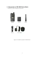
Page 4: ...4 2 Components of XR 2400 Series Radio Components could be changed by buyer request Figure 2 1 standard components of XR 2400 Radio...

Page 5: ...5 3 Appearance of XR 2400 Radio Figure 3 1 Appearance of XR 2400 Radio...

Page 6: ...6 Figure 3 2 XR 2400 Series LCD Indication 4 Basic Operation of XR 2400 Pease read this manual carefully before using XR 2400 series Radio This manual contains important information about using Radio...

Page 7: ...pressing it against and sliding it towards the bottom of the radio Figure 4 2 Installation and Removing the Battery 4 2 Installation and Removing the Belt Clip To attach belt clip to radio align belt...

Page 8: ...volume level 5 2 PTT Button Push To Talk Button You can transmit by pressing PTT button And then Red LED will be ON and your voice will be transmitted 5 3 Channel Buttons Channel Buttons have 2 functi...

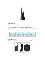
Page 9: ...Radio 2 Please charge the battery before using the radio for best performance and safety 1 When you charge the battery that is installed in the Radio please turn off the radio first to charge the bat...

Page 10: ...ot 3 After completion of the charging the green LED on the charger will light However please continue the charging for 30 more minutes for the complete full charge status LED indication status LED ind...

Page 11: ...n on the radio by above way 6 2 Transmission Method For transmission press PTT button on the left side of the radio As soon as the user presses keys according to the setting DTMF ID will be transmitte...

Page 12: ...interference to radio communications However there is no guarantee that interference will not occur in a particular installation If this equipment does cause harmful interference to radio or televisi...

Page 13: ...to minimize these hazards This transceiver is not intended for use by the general public in uncontrolled environments Uncontrolled environment exposure limits are applicable to situations in which the...

Reviews: