background image

11

SUSPENSION MAINTENANCE

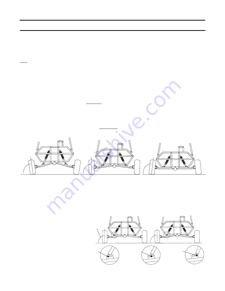
A. EXTREME OUTWARD CAMBER

(NEW SHOCKS, NOT BROKEN IN)

B. SLIGHT OUTWARD CAMBER

 (SHOCKS BROKEN IN)

C. INWARD CAMBER

(SHOCKS NEED TO BE

ADJUSTED OR REPLACED)

The Suspension System on your Fun-Kart is specifically designed and set up for the smoothest possible

ride, while maintaining top performance and kart durability. Your Fun-Karts suspension system uses four

shock absorbers, two on the front suspension and two on the rear suspension, to comfortably tackle rough

terrain.
The two front shock absorbers affect the camber or slant of your front tires. You may have noticed that your

new Fun-Kart has an 

extreme outward camber

 or slant of the front tires as shown in 

Figure A

.

 This is

normal.

  They were set this way at the factory for ensuring maximum tread life on the front tires. There are

three important reasons for this outward camber:

1.   The weight of the driver and/or passenger is not on the Kart.

The added weight of the driver and/or passenger pushes the front and rear suspension down.

2.   The Fun-Kart is not in motion.

When the Kart is in motion, the front suspension is forced down slightly.

3.   The shock absorbers are new and not “broken in”.

Your new Fun-Kart needs at least one hour of use to “break in” the shocks and level out the tires.  After

the first 30 minutes of use, the outward camber may be reduced by one half.  After 1 hour of use the

tires may have 

almost no or slight outward cambe

r as shown in 

Figure B

.

When your Fun-Kart gets an 

inward camber

 on the front tires from shock wear as shown in 

Figure C

 and

steering becomes difficult, the shocks will need to be readjusted.  Adjust the front suspension to a 

slight

outward camber

 as shown in

 Figure B

 by increasing the shocks. Adjust the shocks by following the

“Shock Absorber Adjustment “ instructions below. When your shocks cannot be adjusted any tighter, they

must be replaced.

D. THREE QUICK CAMBER ADJUSTMENTS

NOTE: Outside holes can be

used for new kart display

purposes with new shocks.

(Setting at “NO CAMBER”)

POSITION 2

(MIDDLE

HOLE)

POSITION 3

(INSIDE

HOLE)

POSITION 1

(OUTSIDE

HOLE)

To adjust: Remove 3/8” x 1-3/4”

Bolts and 3/8” Nylock Nuts attach-

ing the bottom of the Shocks to the

Three Hole Brackets and move to

desired hole then reattach Shocks.

Tighten Bolts.

Your Fun Kart has an added feature on the A-Arms for three quick Camber Adjustments 

Figure D

.

Note: The factory attaches the shocks at position 2. You may choose to move them to position 1 and

adjust shocks to set at Slight Outward Camber (Riding Position) until the shocks “break in” then either

readjust the shocks as shown in “Shock Absorber Adjustment” or move to position 2.  Shocks may

bottom out (cannot be adjusted any tighter)

before you need to set to position 3.

NO CAMBER

SLIGHT

OUTWARD

CAMBER

DISPLAY POSITION

RIDING POSITION

Summary of Contents for 32001 Series

Page 1: ...nts 6 Liters OF SAE 30 MOTOR OIL This vehicle is sold for off road use only Before operating this vehicle read all the instructions for safe assembly and operation as well as the instructions governin...

Page 2: ...s Fun Kart is not intended nor designed for racing 4 The operator of this vehicle should always wear a D O T approved helmet and other protective equipment as recommended by state and local laws The o...

Page 3: ...ty and physical capability to act to protect himself herself and wear a D O T approved helmet at all times This kart is not recommended for weights exceeding 200 pounds 13 The engine should be stopped...

Page 4: ...e removed 23 When storing the vehicle it must be kept in a place where gasoline fumes will not reach an open flame or spark For long periods of storage such as for winter the fuel tank should be drain...

Page 5: ...n wet surfaces and allow for extra braking distance 33 ALWAYS mount the caution flag provided on the Fun Kart for safety purposes This flag could help prevent dangerous situations Pay close attention...

Page 6: ...f purchase A Frame for 90 days Void if 1 Frame is broken or bent due to abuse underside scraped abusively 2 Wheels are bent or broken due to impact 3 Spindles are bent due to impact 4 Paint is worn of...

Page 7: ...nuts and bolts on your vehicle to see that all are tightened securely For safe operating conditions do periodic checks and tighten securely 7 Engine Fill the crankcase with oil until it reaches the F...

Page 8: ...witch Perform this stop switch test While the engine is running move the steering column remote stop switch to the OFF position If this does not stop the engine move the engine remote switch to the OF...

Page 9: ...urning at slow constant speeds Defer increased speeds until you are confident of your proficiency and are intimately familiar with the terrain Steer in the direction of the turn and lean your body to...

Page 10: ...the first two hours of operating your new engine and after each 25 hours of use thereafter That will insure proper lubrication in internal parts and prevent costly repairs due to excessive wear Refer...

Page 11: ...nutes of use the outward camber may be reduced by one half After 1 hour of use the tires may have almost no or slight outward camber as shown in Figure B When your Fun Kart gets an inward camber on th...

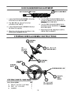
Page 12: ...BERS 72 at the front and rear of the FUN KART 2 The SHOCKS are pre set for normal conditions at the factory 3 Locate the SHOCK ADJUSTMENT HOLE at the base of the spring 4 Place the end of a narrow scr...

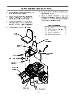
Page 13: ...dware shown 1 Locate the SEAT FRAME ASSEMBLY LAP BELT and SHOULDER BELT 2 Align STUDS on the bottom of the SEAT FRAME ASSEMBLY with the SEAT TAB HOLES on the FUN KART FRAME 3 Slip SHOULDER BELT and LA...

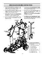
Page 14: ...wn 2 Secure the REAR BRUSH GUARD 51 and SAFETY FLAG 34 to the rear tabs on the FRAME using the hardware shown 3 Align holes and secure the REAR BRUSH GUARDS 51 to the top of the MAIN BRUSH GUARD 21 us...

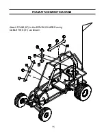
Page 15: ...15 Attach FOAM 87 to the BRUSH GUARDS using CABLE TIES 81 as shown FOAM ATTACHMENT DIAGRAM...

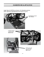
Page 16: ...n in the illustrations below Note Decals are self adhesive and require no glue SUGGESTED DECALAPPLICATION Yerf Dog logo 2 applied to both sides of front Yerf Dog logo 2 applied to both sides of rear Y...

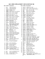
Page 17: ...BLACK 27 00918 DECAL KIT 83 H92561W STEERING WHEEL 13 W CAP 28 Q43203W DRIVE BELT COMET 84 36000700 THROTTLE CABLE 40 29 00994 DRIVE CHAIN 85 23001700 TIE ROD ASSEMBLY 30 02908 DRIVE COVER BLACK 86 00...

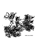
Page 18: ...18 MODEL 32001 SERIES...

Page 19: ...16 YEARS OLD WEAR A D O T APPROVED HELMET PROTECTIVE EYE WEAR AND CLOTHING SECURE LONG HAIR AND LOOSE CLOTHING KEEP ARMS LEGS AND FEET INSIDE THE KART DO NOT OPERATE UNDER THE INFLUENCE OF DRUGS ORAL...

Reviews: