background image

10

SUSPENSION MAINTENANCE

The Suspension System on your Go-Kart is specifically designed and set up for the smoothest possible
ride, while maintaining top performance and kart durability. Your Go-Karts suspension system uses
four shock absorbers, two on the front suspension and two on the rear suspension, to comfortably
tackle rough terrain.

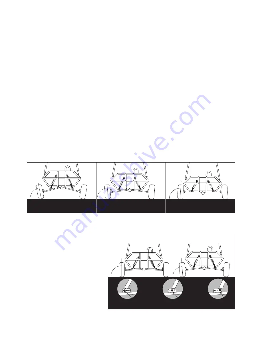
The two front shock absorbers affect the camber or slant of your front tires. You may have noticed
that your new Go-Kart has an extreme outward camber or slant of the front tires as shown in Figure
A
. This is normal.  They were set this way at the factory for ensuring maximum tread life on the front
tires. There are three important reasons for this outward camber:

1.   The weight of the driver and/or passenger is not on the Kart.

The added weight of the driver and/or passenger pushes the front and rear suspension down.

2.   The Go-Kart is not in motion.

When the Kart is in motion, the front suspension is forced down slightly.

3.   The shock absorbers are new and not “broken in”.

Your new Go-Kart needs at least one hour of use to “break in” the shocks and level out the tires.
 After the first 30 minutes of use, the outward camber may be reduced by one half.  After 1 hour
of use the tires may have almost no or slight outward camber as shown in Figure B.

When your Go-Kart gets an inward camber on the front tires from shock wear as shown in Figure C
and steering becomes difficult, the shocks will need to be readjusted.  Adjust the front suspension to
slight outward camber as shown in Figure B by increasing the shocks. Adjust the shocks by following
the “Shock Absorber Adjustment “ instructions below. When your shocks cannot be adjusted any
tighter, they must be replaced.

Your Fun Kart has an added feature on the A-Arms for three quick Camber Adjustments Figure D.
Note: The factory attaches the shocks at position 2. You may choose to move them to position 1
and adjust shocks to set at Slight Outward Camber (Riding Position) until the shocks “break in” then
either readjust the shocks as shown
in “Shock Absorber Adjustment” or
move to position 2.  Shocks may
bottom out (cannot be adjusted any
tighter) before you need to set to
position 3.

To adjust: Remove 3/8” x 1-3/4”
Bolts and 3/8” Nylock Nuts attaching
the  bottom of the Shocks to the
Three Hole Brackets and move to
desired hole then reattach Shocks.
Tighten Bolts.

NOTEOutside holes can be used for
new kart display purposes with new
shocks. (Setting at “NO CAMBER”)

A. EXTREME OUTWARD CAMBER

(NEW SHOCKS, NOT BROKEN IN)

C. INWARD CAMBER

(SHOCKS NEED TO BE

ADJUSTED OR REPLACED)

B. SLIGHT OUTWARD CAMBER

(SHOCKS BROKEN IN)

POSITION 1

OUTSIDE HOLE

POSITION 2

MIDDLE HOLE

POSITION 3

INSIDE HOLE

FIGURE D – THREE QUICK CAMBER ADJUSTMENTS

DISPLAY POSITION

RIDING POSITION

Summary of Contents for 3204

Page 1: ...gine and other portions of the vehicle Pay close attention to all caution and warning labels 7 31 03 04081 Rev D Read Tecumseh Engine Owner s Manual and Important Rules for Safe Operation before Opera...

Page 2: ...ht to ensure that the vehicle is in safe operating condition The engine must be kept free of all dirt and other accumulations paying particular attention to throttle linkage area 6 Prevailing Torque t...

Page 3: ...6 Wet slippery rough or steep terrain is potentially dangerous and may result in injury if proper caution is not observed Slow speeds are required to safely operate this vehicle under those conditions...

Page 4: ...as a service manual 28 Assembly maintenance and or repair of this Go Kart should only be performed by persons of sufficient mechanical skill experience and judgment such as outdoor equipment dealers...

Page 5: ...due to impact 4 Paint is worn off of rear bumper indicating an extra rider 5 Axles are bent out of ordinary position either horizontally or vertically 6 Non Factory altering of engine or it s compone...

Page 6: ...z or 11 4 pints 6 Liters of SAE 30 weight oil For additional information refer to Tecumseh engine manual for servicing the engine 5 Fill fuel tank with regular gasoline leaded or unleaded Do not use p...

Page 7: ...witch Perform this stop switch test While the engine is running move the steering column remote stop switch to the OFF position If this does not stop the engine move the engine remote switch to the OF...

Page 8: ...urning at slow constant speeds Defer increased speeds until you are confident of your proficiency and are intimately familiar with the terrain Steer in the direction of the turn and lean your body to...

Page 9: ...fter the first two hours of operating your new engine and after each 25 hours of use thereafter That will insure proper lubrication in internal parts and prevent costly repairs due to excessive wear R...

Page 10: ...hown in Figure B When your Go Kart gets an inward camber on the front tires from shock wear as shown in Figure C and steering becomes difficult the shocks will need to be readjusted Adjust the front s...

Page 11: ...6 Turn the SHOCK ADJUSTMENT HOLE clockwise around the SHOCK to increase shock absorption 7 Experiment with the adjustment until the desired effect is attained SHOCK ABSORBER ADJUSTMENT STEERING WHEEL...

Page 12: ...d 76 76 77 Female End Item 11 18 57 60 77 76 Description BOLT 3 8 16 X 1 HEX BOLT 5 16 18 X 1 1 2 CARRIAGE NUT 3 8 16 NYLOCK NUT 5 16 18 NYLOCK SEAT BELT RETRACTABLE SEAT RAIL SEAT BELT ATTACHMENT HAR...

Page 13: ...ce nut 60 on end of carriage bolts 18 and tighten all 4 nuts front and rear STEP 2 Note Make sure the seat belts are extending to the outside of the seat frame To move the slide on the rail with the a...

Page 14: ...WASHERS 101 AND four 5 16 NYLOCK NUTS 60 Item 60 101 Description Nut 5 16 18 Nylock Washer 5 16 Flat SEAT ATTACHMENT HARDWARE Qty 4 4 Threaded Studs on seat bottom Seat Bracket Holes Slide SEAT CUSHI...

Page 15: ...ds of the shoulder belt The BELT must rotate SHOULDER BELT ATTACHMENT Attach both driver and passenger shoulder belts using BOLTS 20 WASHERS 101 and NUTS 60 Finished Assembly BRUSH GUARD CROSS ATTACHM...

Page 16: ...ross Brush Guards as shown on this page and the previous page BEFORE tightening bolts 2 Attach flag as shown on this page FLAG ATTACHMENT 4 Wrap CABLE TIE 37 around FLAG BRACKET and REAR BRUSH GUARD 5...

Page 17: ...wn 2 Finish splitting FOAM 48 Foam is partially split 3 Attach FOAM to the BRUSH GUARDS using CABLE TIES 35 48 35 Caution Take care to not cut yourself when cutting and splitting foam with a sharp ins...

Page 18: ...xpose adhesive surface NOTE DO NOT REMOVE DECAL BACKING COMPLETELY This will cause decal to curl and stick to itself 2 Align the decal with floor pan Gently press adhesive to floor pan to start applic...

Page 19: ...W SCREW SELF TAPPING 1 4 111 02625 SLEEVE AXLE 4 112 01474 SPACER 3 8 113 01069 STEERING WHEEL CAP 02604 4 CYCLE ENGINE OIL 04081 OWNERS MANUAL 1 01263 A ARM LEFT BLACK 2 01264 A ARM RIGHT BLACK 3 011...

Page 20: ...20 MODEL 3204...

Page 21: ...de and do not ride a slope that is greater than 15 degrees A 15 degree slope is a hill that increases in height at approximately 2 5 feet in 10 feet A 10 degree slope is a hill that increases in heigh...

Page 22: ...the following precautions OPERATE THIS KART OFF ROAD ONLY ADULT SUPERVISION FOR OPERATORS UNDER 16 YEARS OLD WEAR A D O T APPROVED HELMET PROTECTIVE EYE WEAR AND CLOTHING SECURE LONG HAIR AND LOOSE C...

Reviews: