YETI 160E | OWNER’S MANUAL
12
E-COMPONENT ASSEMBLY
TABLE OF CONTENTS |
03
Route rear brake housing forward, ensuring a
generous strain relief from caliper to cable port
entry to account for motion between chainstay and
seatstay. Secure to chainstay with a Single Port
Cover (4.27) and M4 FHCS (4.20)
04
Route brake housing into Front Triangle ensuring
adequate strain relief between front and rear
triangle. Route brake housing up either the left-
most or right-most channel in cable trays and exit
the non-drive side port hole on the headtube.
01
If installing a wired drivetrain, route a length of
shifter housing from the non-drive side headtube
port (lower hole), down the downtube being
secured in the second-from-left opening in the
cable trays.
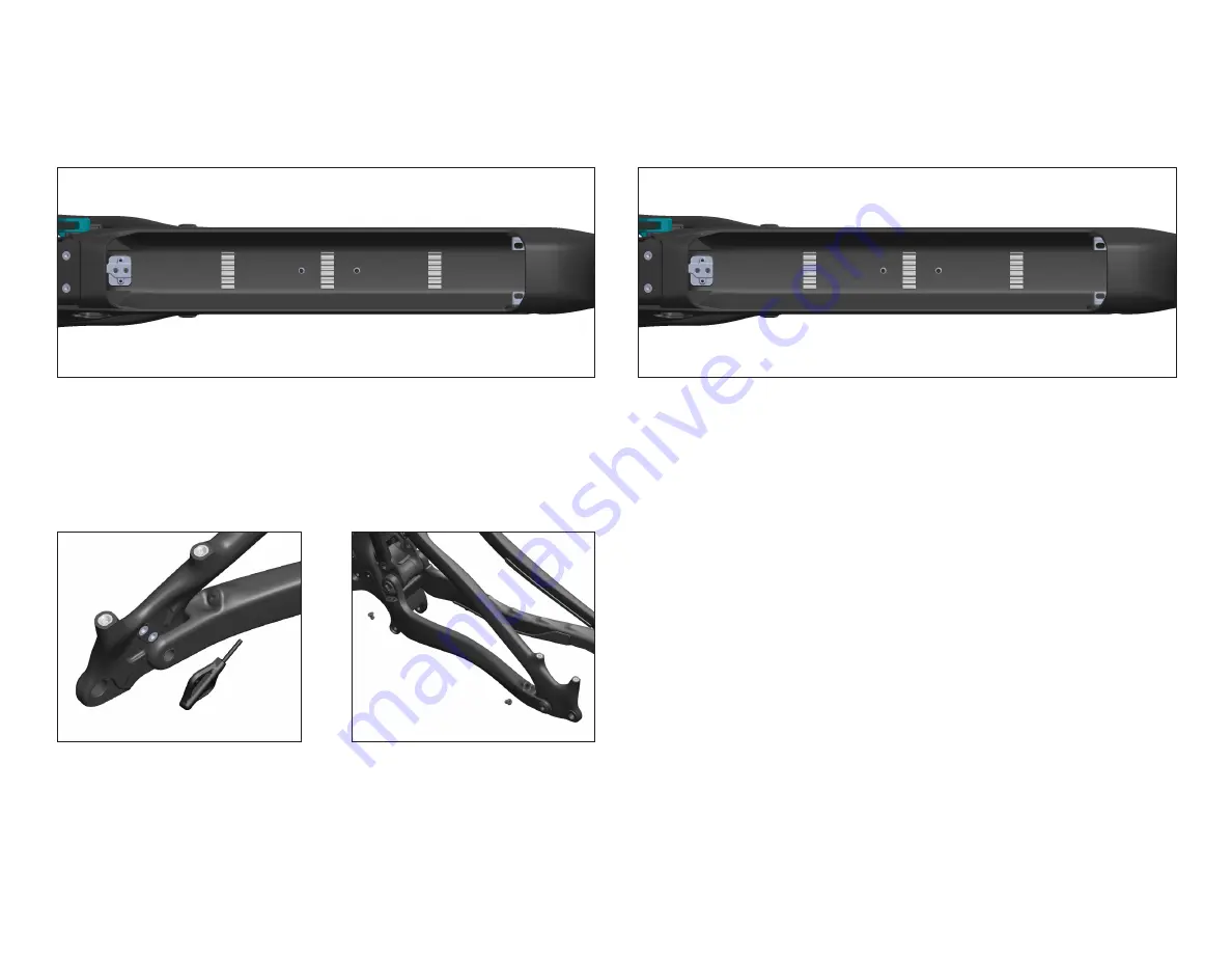
02
Route shifter housing past the lower battery
mount pad and into the motor cavity. Exit the
housing from the front triangle port and loop over
the top of the Collet Nut clamp features and into
the drive-side chainstay.
05
Install Speed Sensor (4.6.7) to the Seatstay with
supplied Shimano M3 fasteners.
Tighten to 0.6Nm (hand tight).
Route E-wire through the chainstay ensuring adequate
strain relief. Exit the chainstay and loop sensor wire
with brake housing into the Front Triangle.
06
Install 2X Grommet (4.32) around sensor wire
at each chainstay port and push into frame
until flush.
FIRST OPERATIONS MAY BE PERFORMED IN A STAND OR FLIPPED UPSIDE DOWN,
DEPENDING ON BUILDER PERSONAL PREFERENCE.
E-COMPONENT ASSEMBLY
Summary of Contents for 160E
Page 1: ...YETI 160E OWNER S MANUAL...


