background image

SMARTBENCH V1.3 – STANDARD, PRECISION AND PRECISIONPRO

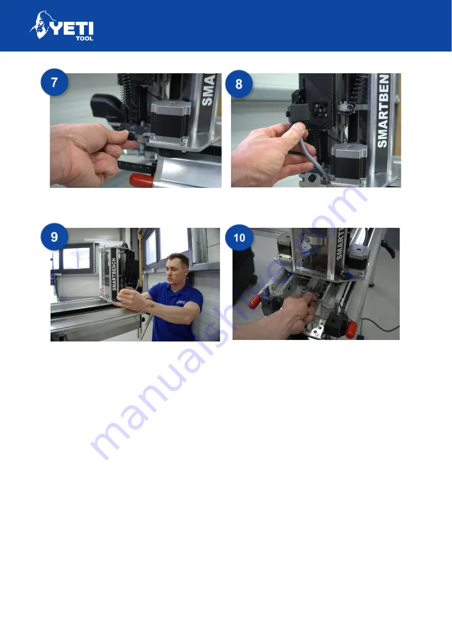
Secure this in place with the thumbscrew

provided.

Plug in the power cable and secure it with

the thumbscrew.

You can now push the

Z Head

onto the

Upper X Beam

until all wheels are

engaged. If you do not push the Z-Head

further onto the Upper beam the motors

will not be engaged with the rack.

Fit the dust shoe plug into the front of the
dust shoe. This can be made easier when

it is over the bench so you have a flat

surface as a base.

Unit 12 Old Mill Road  |  Portishead  |  Bristol  |  BS20 7BX  |  UK

14

Summary of Contents for SMARTBENCH V1.3

Page 1: ......

Page 2: ...sembly 8 Fit Leg Set 1 8 Fit the Lower X Beam 9 Fit Leg Set 2 10 Attach the Upper X Beam 11 Fit the Z Head 12 Fit the Console 14 Fit the Link Cable 15 Fit the Extractor 15 Fit the SmartBench Power Cable 17 Correct fitting of cables 17 Strain relief 18 Check cable connections 19 Turning on SmartBench 20 Status LED s 23 Update software 23 Updating via Wi Fi 24 Updating via USB 24 Unit 12 Old Mill Ro...

Page 3: ... Disconnect cables 36 Step 2 Loosen spindle cage collar 36 Step 3 Replace spindle 37 Step 4 Connect cables 37 Troubleshooting 38 SmartBench will not power on 38 Console will not boot 38 SmartBench will not home correctly 38 Software will not update 38 Console will not connect to the Wi Fi 39 USB will not read 39 SmartBench is in an alarm state 39 Spindle does not power on 39 Extraction does not po...

Page 4: ...A2 2013 EN 62311 2008 EN 62061 2005 EN ISO 19085 1 2017 EMC RED article 3 1b ETSI EN 301 489 1 V2 1 1 2017 02 in accordance with the specific requirements of ETSI EN 301 489 17 V3 1 1 2017 02 EN 55032 2012 AC 2013 Class A EN 55035 2017 EN 61000 3 2 2014 EN 61000 3 3 2013 Spectrum RED article 3 2 ETSI EN 300 328 V2 1 1 2016 11 ETSI EN 301 893 V1 8 1 2015 03 RoHS2 EN 50581 2012 Other EN IEC 63000 20...

Page 5: ...quipment Regulations 2012 We hereby declare that the product described above to which this declaration of conformity refers to is in conformity with the essential requirements of the following designated standards Type Essential Requirements Health Safety RED article 3 1a EN 62368 1 2014 EN 60950 1 2006 A1 2010 A12 2011 A2 2013 EN 62311 2008 EN 62061 2005 EN ISO 19085 1 2017 EMC RED article 3 1b E...

Page 6: ...guide we also have a digital version available here https www yetitool com support downloads Video tutorial Please note all of the information in this Quick Start Guide can also be seen in a video tutorial on our Youtube channel in more detail Unit 12 Old Mill Road Portishead Bristol BS20 7BX UK 5 ...

Page 7: ...s with SmartBench or learn more about best use examples YetiTool CNC Academy We ve created CNC Academy to help those that may be new to CNC or who just want to expand their knowledge After the first setup our courses will take you through everything you need to know step by step to cutting your first project Unit 12 Old Mill Road Portishead Bristol BS20 7BX UK 6 ...

Page 8: ... key components of SmartBench Please check the contents If any of the above items are damaged or missing please contact your point of purchase immediately Box 1 1 x Z Head assembly 1 x SmartBench Console 1 x Dust shoe plug Box 3 2 x Leg Set 1 x Spindle 1x IEC Power lead 1x Extraction power lead 1 x USB Stick 1 x Tool kit Collet Spanner and 6mm hex 1 x Wheel setting tool 1 x Console Safety Bond Box...

Page 9: ...TANDARD PRECISION AND PRECISIONPRO Key components Figure 1 Y Bench Figure 2 Z Head Figure 3 Leg Set x2 Figure 4 Console Figure 5 Upper X Beam Figure 6 Lower X Beam Unit 12 Old Mill Road Portishead Bristol BS20 7BX UK 8 ...

Page 10: ...osite end of the bench fit Leg Set 1 by first unfolding the legs Lift the Y Bench to accept the location pins of the Leg Set Slide the leg clamp pins into the slots in the Y Bench end plate Push the clamp handles down to the Y Bench end plate to tighten They are designed to not sit perfectly flat to give room to unclamp Unit 12 Old Mill Road Portishead Bristol BS20 7BX UK 9 ...

Page 11: ... just past the first crossbeam To fit the Lower X Beam offer up the beam ensuring the home labels are aligned Ensuring the wheels align with the channels push Lower X Beam onto the Y Bench You should feel some preload on the wheels as they pop into place Push the Lower X Beam onto the Y Bench The assembly should look like this Unit 12 Old Mill Road Portishead Bristol BS20 7BX UK 10 ...

Page 12: ...the end plate and take Leg set 2 with the other hand Lift the Y Bench to accept the location pins of the Leg Set Slide the leg clamp pins into the slots in the Y Bench end plate Use the clamp handles to attach the bench to the legs Unit 12 Old Mill Road Portishead Bristol BS20 7BX UK 11 ...

Page 13: ...above Secure in place by tightening the clamps on each end of the beam The forks on the end of the Upper X Beam should slide on the skids of the Lower X Beam Slide the cables by the drag chain latch plate so that they are laid flat and extend from the end of the Upper X Beam Unit 12 Old Mill Road Portishead Bristol BS20 7BX UK 12 ...

Page 14: ...he beam This should be just passed the first wheel Place the drag chain latch plate over the rectangular face on the side of the Z Head bottom plate ensuring the signal cable seats into the recess Secure this in place with the thumbscrew provided Plug in the signal cable and secure it with the thumbscrew Place the drag chain latch plate over the protruding face on the side of the Z Head Unit 12 Ol...

Page 15: ...ow push the Z Head onto the Upper X Beam until all wheels are engaged If you do not push the Z Head further onto the Upper beam the motors will not be engaged with the rack Fit the dust shoe plug into the front of the dust shoe This can be made easier when it is over the bench so you have a flat surface as a base Unit 12 Old Mill Road Portishead Bristol BS20 7BX UK 14 ...

Page 16: ...ug the console cable into the XLR connector as shown above The safety bond is to loop through the end plate on the lower beam This attaches to the console mounting bracket using the carabiner Note We include a safety bond for the console in the box This is not mandatory however YetiTool Ltd will not be held responsible for any console breakages Unit 12 Old Mill Road Portishead Bristol BS20 7BX UK ...

Page 17: ...ower outlet for extractors to automatically switch your extraction on or off but the extractor must not draw more than 13 amps If the extractor draws more than 13 amps the extractor must be powered from a separate power outlet and operated manually Attach the extraction hose to the underside of the Lower X Beam Attach the extraction hose to the Z Head by inserting the connector into the elbow and ...

Page 18: ...ied cable and plug the supplied extension cable to the output socket to connect to your extractor To power your extraction automatically you need both the input and output cables plugged in The input cable powers the output through a relay which switches on and off as required OR Plug in your extractor to a separate power outlet Unit 12 Old Mill Road Portishead Bristol BS20 7BX UK 17 ...

Page 19: ...ine power cable input is on the underside of the Lower X Beam Plug the cable into the connector on the underside of the Lower X Beam Correct fitting of cables Make sure that all cables are fully inserted Incorrect fitting Correct fitting Unit 12 Old Mill Road Portishead Bristol BS20 7BX UK 18 ...

Page 20: ...d into the strain relief clips on the Lower X Beam Using the strain relief correctly will ensure the cables cannot be removed during operation in case of a pull or snag Keep everything under the machine clear to prevent any catches with the cables Unit 12 Old Mill Road Portishead Bristol BS20 7BX UK 19 ...

Page 21: ... connector 4 Extraction power input if using the auto extraction system 5 Extraction power output if using the auto extraction system 6 Console XLR 7 Mains Power Fig 1 Z Head signal Fig 2 Z Head power Fig 3 X beam link Fig 4 Extraction power input Fig 5 Extraction power output Fig 6 Console socket Figure 7 SmartBench power Unit 12 Old Mill Road Portishead Bristol BS20 7BX UK 20 ...

Page 22: ...ered on by releasing the Emergency stop button To release the button it must be twisted clockwise Figure 14 E Stop Button Turning off SmartBench When you are done with Smartbench Turn the console off from the power button first to prevent any damage then after 60 seconds push the E stop button inwards Unit 12 Old Mill Road Portishead Bristol BS20 7BX UK 21 ...

Page 23: ...O Connecting to Wi fi Connecting SmartBench your local network gives the following functionality Software updates File transfer via your Wi Fi network 1 Navigate to the Wi Fi app in the main lobby Unit 12 Old Mill Road Portishead Bristol BS20 7BX UK 22 ...

Page 24: ... connect button Please note the system will then automatically restart The console screen will go black as the console restarts this is normal do not power the machine down during restart Status LED s The LED s on the Z Head indicate the status of SmartBench Green Status is good a job is running no action is to be taken Yellow SmartBench needs to be homed action needs to be taken Red SmartBench is...

Page 25: ...ware either via Wi Fi or USB Updating via Wi Fi Photo used for reference your update number may change Ensure you have a stable Wi Fi connection Press the update button The system will automatically connect to our server download and update the latest version and then reboot Unit 12 Old Mill Road Portishead Bristol BS20 7BX UK 24 ...

Page 26: ...our USB stick 3 Insert the USB into the console and press update The system will automatically update the latest version of and then reboot It is important to note None of your job files will be touched and The last set datum or park points will be retained If you have any issues updating please submit a support ticket Home SmartBench 1 From the Lobby screen press to go to CAD CAM operation 2 Pres...

Page 27: ...ion with a high degree of reliability Thus mechanical adjustments to square the beam can be repeated Auto Square No special preparation from the user is needed When homing the lower beam automatically drives into the legs to square the X beam against the bench legs The stalling procedure can offer a general squareness But at the end of the movement the motor coils can bounce into a different step ...

Page 28: ...irectly from your computer Via the legacy Filezilla FileZilla is our legacy format and while slower can still be used if required to send job files directly to the SmartBench console from your computer via your Wi Fi network The only file types visible on the console are nc files and gcodes Note any in your filename will confuse the console for example my cut file gcode will not be visible Open a ...

Page 29: ...H V1 3 STANDARD PRECISION AND PRECISIONPRO 3 Choose your file The ones below are just examples and won t be on your console 4 Accept your file choice Green Unit 12 Old Mill Road Portishead Bristol BS20 7BX UK 28 ...

Page 30: ...oint and setting the datum to that position 1 Go to Move Screen 2 Note that double presses of the arrows will send the machine in that direction infinitely The icon can be pressed to change the distance moved to an exact figure 3 Move the X Axis Red 4 Move the Y axis Green 5 Set the job start point the Z Head LED will flash GREEN to confirm Unit 12 Old Mill Road Portishead Bristol BS20 7BX UK 29 ...

Page 31: ...not see the red box in the map screen check that you are exporting in MM rather than inches Only export your job files in MM Set Z datum start point for the job Once the X Y datum is defined the tip of the router cutter needs to be registered relative to the material This is referred to as setting the Z datum and should be done near the X Y datum Start by going to the X Y datum 1 Go to the Map Scr...

Page 32: ...n the surface you are trying to probe The probe plate should be silver side up 6 If the tip of the cutter is not close to the top of the stock manually move it downwards to about 10mm 3 8 away from the probe using the Z down button Red in the picture below Take care not to overshoot 7 When close press the Z0 button Green The Z Head will automatically lower slowly until the tool tip touches the pro...

Page 33: ...SMARTBENCH V1 3 STANDARD PRECISION AND PRECISIONPRO Unit 12 Old Mill Road Portishead Bristol BS20 7BX UK 32 ...

Page 34: ...CH V1 3 STANDARD PRECISION AND PRECISIONPRO Run job 1 To run your job press the play button 2 Confirm you wish to run your file by pressing the GO button Unit 12 Old Mill Road Portishead Bristol BS20 7BX UK 33 ...

Page 35: ...e offset will allow SmartBench to accurately calculate the distance in X and Y between the centre of your tool and the crosshair To set if laser hardware is fitted 1 Enable laser datum Switch to on 2 On a test piece of material cut a mark using manual moves We would recommend using a v groove bit for higher accuracy 3 Lift head and press the reset button in the bottom left Unit 12 Old Mill Road Po...

Page 36: ...using the arrows so that the laser cross hair lines up with the mark centre 5 Press Save Your laser datum offset will then be saved into the system You can reset this by repeating the steps above More details are available in this video Unit 12 Old Mill Road Portishead Bristol BS20 7BX UK 35 ...

Page 37: ...cable You can ignore references to this wire if you have the Standard version of SmartBench To change the spindle you will want to move the Z Head closer to the X0 X home position for easier access To do this use the arrows highlighted below red to move the Z Head along the X axis You will need 6mm hex driver this is provided with your SmartBench Unit 12 Old Mill Road Portishead Bristol BS20 7BX U...

Page 38: ...t the power cable from the IEC connector Remove the speed control cable Step 2 Loosen spindle cage collar Insert the 6mm hex driver into the spindle cage bolt and rotate left to loosen the bolt Then lift your spindle out of the top of the cage The spindle may need to be rotated to remove it Unit 12 Old Mill Road Portishead Bristol BS20 7BX UK 37 ...

Page 39: ...mping torque has been achieved you can no longer spin the spindle around inside the cage apply an extra turn maximum 45 turn DO NOT over tighten this will damage the bearings in your spindle See the included spindle document for more info Step 4 Connect cables Reconnect the speed control cable ensuring to tighten the threaded collar Push the power cable back into the IEC connector Unit 12 Old Mill...

Page 40: ... secure Ensure the emergency stop button is released with the green part of the button released Check the fuses these can be found on the underside of the lower beam Ensure your console is connected to the XLR connector on the upper beam Ensure the Z Head power and signal cables are connected and the retaining screws tightened Ensure the connection pins are not bent out of shape on the Z Head Cons...

Page 41: ...updating via USB ensure you have saved the file to the root of the USB drive Console will not connect to the Wi Fi Ensure you have selected the correct Wi Fi network Ensure you have entered the Wi Fi password correctly The password is case sensitive Ensure you have the correct country code selected GB works for most regions If you are using the console in a place without Wi Fi see these instructio...

Page 42: ...turned on If you are using automatic extraction check that all three cables are plugged into the lower beam One for smartbench power The other to input the extraction power into SmartBench And the final one to output the extractor power from SmartBench Issues with CAD designs If using Vectric check our first project for beginner information Check youtube for tutorials in your chosen cad package Ch...

Page 43: ... calibration application Check if any adjustments are required for the X axis and the Y axis wheels after 320 hours Does the machine require maintenance Support If you require any support please visit our website and raise a support ticket www yetitool com support submit a ticket Unit 12 Old Mill Road Portishead Bristol BS20 7BX UK 42 ...

Reviews: