12
2940 Air Adjust System Information
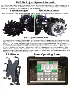
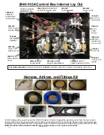
The 2940 Air Adjust Residue Manager control system consists of five primary components and kits; Residue Manager(RM) or
RM/Coulter Combo Kit, Tablet or ISOBUS controller, Yetter Air Compressor Assembly (unless plumbing into an OEM hydraulic
compressor), Control Box Kit, & the Harnessing, Air Lines, & Fittings Kit.
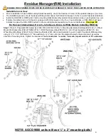
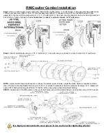
Residue Manager RM/Coulter Combo
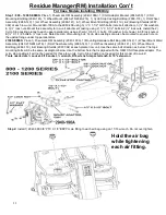
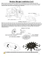
Each of these kits will include the required brackets, wheel assemblies, & mounting hardware for installation to the row unit.
Tablet (NOT SUPPLIED)
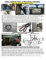
The Tablet of choice, not supplied, will use the 2940-111 RAM mount for 9
– 10” tablets provided for installation in cab. If a
larger Tablet size is used, sourcing a larger RAM Tablet Mount will be necessary. RAM-HOL-UN11U can be purchased online
for tablets 11
– 12”. Go into the tablets App Store, search for Yetter Air Adjust, & download the App. Once the system is
installed, turn the key to make sure the 2940-653 Thrasher module
’s indicator lights come on. Once the indicator lights are on,
go into the tablets WiFi settings & connect to AIR ADJUST. Open the Yetter App & you should be taken to the Activation
Screen. Press the ACTIVATE SYSTEM icon & you will be taken to the operating screen. Until the compressor has built a
minimum of 75psi, no pressure will be sent to the air bags. Let the compressor go thru 1 complete cycle & shut off before
applying air to the air bags. Using shop air with the 2940-382 adapter is an alternative method way to supply air to the system
to help prolong the service life on Yetter compressors.
RAM Mount
Tablet Operating Screen
Summary of Contents for GERMINATE UNIFORMITY 2940
Page 35: ...35 6 Row Airline Diagram 6 11 or 6 12 Split Row Airline Diagram...
Page 36: ...36 8 Row Airline Diagram 8 15 8 16 Split Row Airline Diagram...
Page 37: ...37 12 Row Airline Diagram...
Page 39: ...39 16 Row Airline Diagram...
Page 40: ...40 16 31 16 32 Split Row Airline Diagram...
Page 42: ...42 24 Row Airline Diagram...
Page 43: ...43 24 47 24 48 Row Airline Diagram...
Page 45: ...45 32 Row Airline Diagram...
Page 46: ...46 36 Row Airline Diagram...
Page 47: ...47 48 Row Airline Diagram...
Page 48: ...48 54 Row Airline Diagram...
Page 78: ...78 HYDRAULIC PUMP 2940 545 PARTS IDENTIFICATION PART REFERENCE ONLY...
Page 82: ...82 2565 983_REV_B 09 21...

