33
Airline Routing
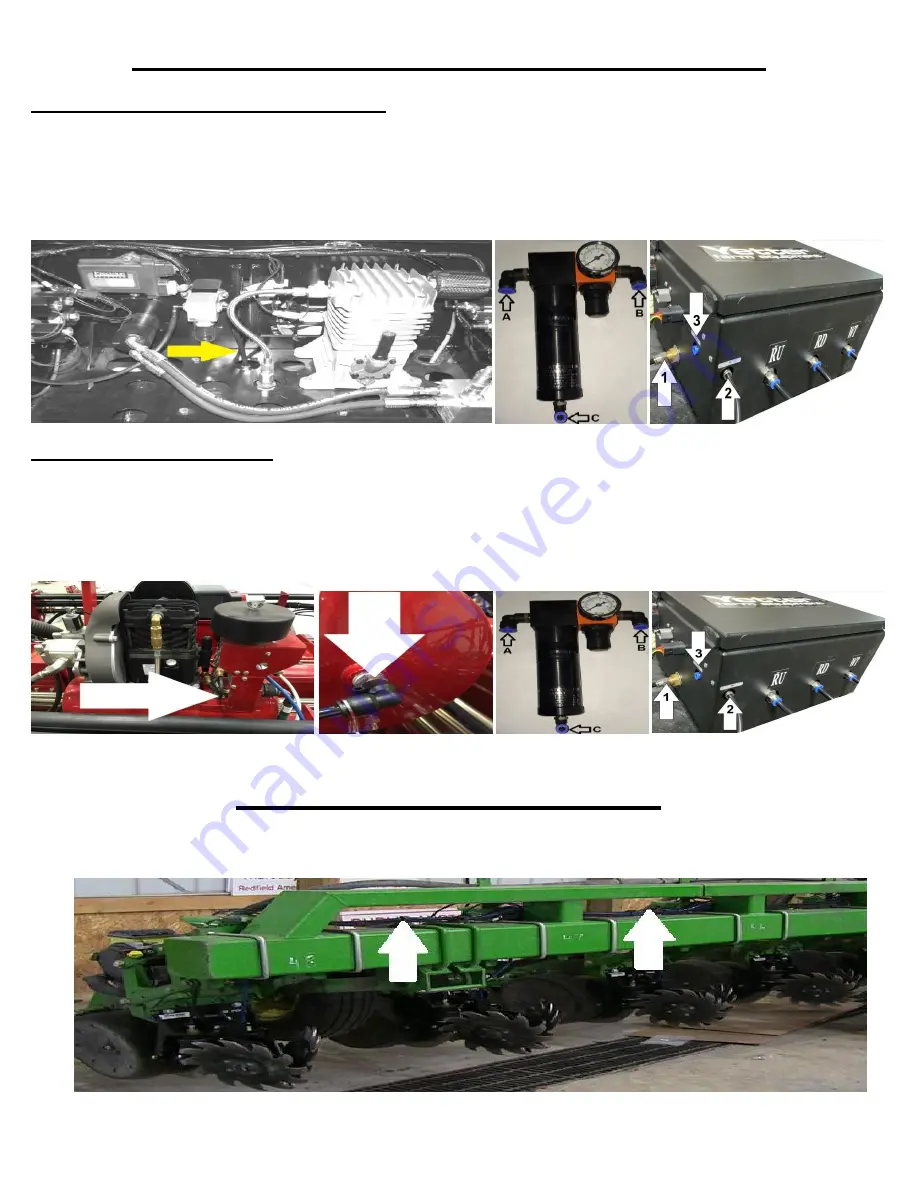
–Compressor to Control Box
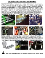
Precision Planting Hydraulic Compressor
Step 1:
Drain all tank pressure from Precision Planting hyd. comp. & install a Tee in the airline that routes from top of tank to
the water separator. (as indicated by arrow below)
Step 2:
Install 2940-
367 250psi rated 3/8” airline from the installed Tee to the inlet (labeled A) of the Yetter water separator.
Step 3:
Install 2940-
345 3/8” black airline from outlet port (labeled B) on water separator to inlet port (labeled 1) on control box.
Step 4:
Route ¼” airline from ¼”PTC elbow (labeled C) on water separator to ¼”PTC fitting (labeled 2) on bottom of control box.
Step 5:
Route ¼” airline from the ¼”PTC fitting (labeled 3) on side of control box toward ground making sure the end of the
airline is not pointed toward anything that moisture may damage or rust.
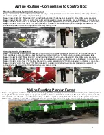
Case Hydraulic Compressor
Step 1:
Drain all tank pressure from Case hyd. comp. Plumb into compressor by either installing a Tee in airline that routes
from top of tank to valve manifold (as indicated by arrow ) or by installing a 2940-408 in bung on side of compressor tank.
Step 2:
Route 2940-
367 250psi rated 3/8” airline from the installed Tee to the inlet (labeled A) of the Yetter water separator.
Step 3:
Route 2940-
345 3/8” black airline from outlet port (labeled B) on water separator to inlet port (labeled 1) on control box.
Step 4:
Route ¼” airline from ¼”PTC elbow (labeled C) on water separator to ¼”PTC fitting (labeled 2) on bottom of control box.
Step 5:
Route ¼” airline from the ¼”PTC fitting (labeled 3) on side of control box toward ground making sure the end of the
airline is not pointed toward anything that moisture may damage or rust.
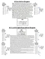
Airline Routing-Planter Frame
Below is a suggested method for safely & securely routing the airlines on the planter frame whether installing trunk airlines (airlines
routing to the row cleaner air bags) or supply airlines (airlines that route from the control box to the trunk airlines). Safely route the
airlines on the frame that the row units are mounted to or follow the path to which the hydraulic hoses on the planter are routed.
After airline installation is complete & system is tested, use provided zip ties to keep parts away from pinch & wear points.
Summary of Contents for GERMINATE UNIFORMITY 2940
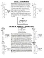
Page 35: ...35 6 Row Airline Diagram 6 11 or 6 12 Split Row Airline Diagram...
Page 36: ...36 8 Row Airline Diagram 8 15 8 16 Split Row Airline Diagram...
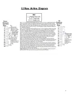
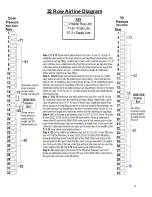
Page 37: ...37 12 Row Airline Diagram...
Page 39: ...39 16 Row Airline Diagram...
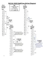
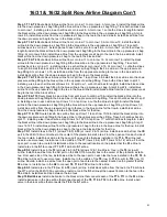
Page 40: ...40 16 31 16 32 Split Row Airline Diagram...
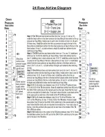
Page 42: ...42 24 Row Airline Diagram...
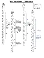
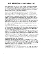
Page 43: ...43 24 47 24 48 Row Airline Diagram...
Page 45: ...45 32 Row Airline Diagram...
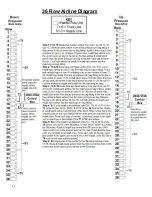
Page 46: ...46 36 Row Airline Diagram...
Page 47: ...47 48 Row Airline Diagram...
Page 48: ...48 54 Row Airline Diagram...
Page 78: ...78 HYDRAULIC PUMP 2940 545 PARTS IDENTIFICATION PART REFERENCE ONLY...
Page 82: ...82 2565 983_REV_B 09 21...


