81
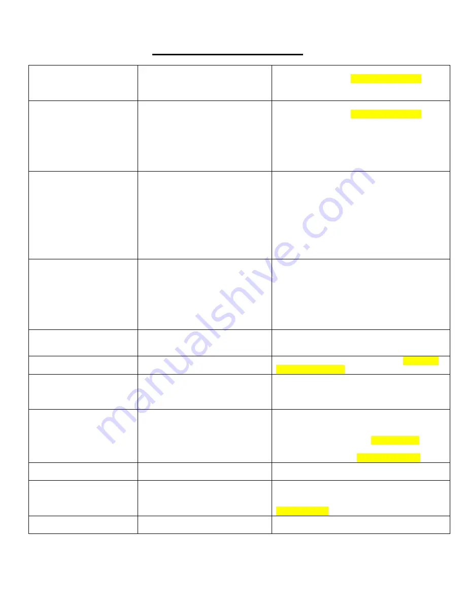
Troubleshooting Guide
Problem
Cause
Corrective Action
Tank pressure drops when
compressor shuts off
1. improper check valve function
2. loose connections/ air leak
3. water separator drain valve
leaking
1. replace check valve on compressor
2. perform leak check
(see pages 53 & 54)
3. replace water separator drain valve
Compressor runs
continuously/air flow lower
than normal, Compressor
Run Time High warning on
cab controller if compressor
runs continuously for 15
minutes
1. excessive air usage
2. loose connections/air leak
3. Improper pressure switch function
4. clogged air filter element
5. worn compressor
6. defective safety valve
7. tank drain valve open
8. water separator valve leaking
1. decrease air usage
2. perform leak check
(see pages 53 & 54)
3. replace pressure switch
4. clean/replace filter element
5. replace compressor
6. replace safety valve
7. close tank drain valve
8. replace water separator valve
Compressor will not run
1. air system is off
2. hydraulics disengaged
3. no power to control box
4. communication harness
connection issue
5. shut off psi(145psi) reached
6. worn compressor
7. Improper pressure switch function
1. press ACTIVATE SYSTEM
2. engage compressor hydraulic circuit
3. check power connections from battery to
control box, check 2940-166 breaker at battery
4. check harnessing from compressor to the
control box
5.compressor will restart after tank pressure drops
below 125psi
6. replace compressor
7. replace pressure switch
No air output from the RU,
RD, and WT ports even
though pressure is
commanded and tank
pressure reads 75psi or
greater
1. air system is off
2. no power to the VDM
3. 75psi of tank pressure not
achieved
4. improperly functioning Mac Valves
5. communication harness
connection issue
1. press ACTIVATE SYSTEM
2. check power connections from battery to VDM,
check 2940-166 breaker at the battery
3. allow the compressor to build at least 75psi
4. replace Mac Valves as needed
5. check the end of all connectors to make sure
terminal pins are all flush to the end of the male
connectors and the connectors are seated tightly
Low or sporadic tank
pressure reading
Air leaking out regulator knob
water separator/regulator assembly
plumbed incorrectly
plumb water separator/regulator correctly
(air compressor
water separator
exit regulator
side
enter control box inlet port)
Compressor struggles to
build/won’t build 145psi
flow control valve adjustment needed flow control valve adjustment needed
(see page
53 for instructions)
No connection to Thrasher or
No connection between VDM
& Thrasher
improper communication harness
connection between VDM and
Thrasher
1. Make sure the lights on the Thrasher are
laminated
2. Make sure 2940-654 Thrasher to Midac is
plugged in
Excessive noise from
compressor
1. loose mounting bolts
2. worn bearings
3. cylinder or piston is worn
4. compressor over speeding
1. tighten bolts
2. replace compressor
3. rebuild compressor
4. check compressor RPMs
(see page 53)
& slow
motor down if needed, hydraulic plumbing of the
compressor is incorrect
(see page 28 - 29)
Excessive moisture in
discharge
1. excessive water in air tank
2. high humidity
1. drain tank, drain tank more frequently
2. move compressor to area with less humidity.
Hydraulic motor front seal
leakage
1. case drain clogged or unplugged
2. case drain not plumbed correctly
1. remove case drain plumbing and clean out
debris/obstruction, replace seal
2. Plumb case drain according to the instructions
(see pages 30)
, replace seal
Row cleaners do not react
uniformly
1. check each row cleaner for drag
1. replace bushings/parts causing drag or check
hardware tightness
Summary of Contents for GERMINATE UNIFORMITY 2940
Page 35: ...35 6 Row Airline Diagram 6 11 or 6 12 Split Row Airline Diagram...
Page 36: ...36 8 Row Airline Diagram 8 15 8 16 Split Row Airline Diagram...
Page 37: ...37 12 Row Airline Diagram...
Page 39: ...39 16 Row Airline Diagram...
Page 40: ...40 16 31 16 32 Split Row Airline Diagram...
Page 42: ...42 24 Row Airline Diagram...
Page 43: ...43 24 47 24 48 Row Airline Diagram...
Page 45: ...45 32 Row Airline Diagram...
Page 46: ...46 36 Row Airline Diagram...
Page 47: ...47 48 Row Airline Diagram...
Page 48: ...48 54 Row Airline Diagram...
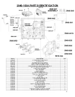
Page 78: ...78 HYDRAULIC PUMP 2940 545 PARTS IDENTIFICATION PART REFERENCE ONLY...
Page 82: ...82 2565 983_REV_B 09 21...


