background image

Summary of Contents for LT32C1M1 Service

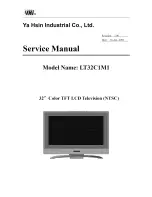
Page 1: ...Ya Hsin Industrial Co Ltd Service Manual Revision 1 00 Date 16 Apr 2006 Model Name LT32C1M1 32 Color TFT LCD Television NTSC...

Page 2: ...rogramming 2 7 Analog Compliant Timings 2 8 Power Management 2 9 Packaging Specification 2 10 Environmental Characteristics AU T315XW01 V5 2 11 Safety 3 0 Functions OSD Operation 3 1 Function Controls...

Page 3: ...and 5 2 2 Remove and Replace Video board 5 2 3 Remove and Replace Rear cover 5 2 4 Remove and Replace Front RCA board and Card Reader Option 5 2 5 Remove and Replace Main board 5 2 6 Remove and Replac...

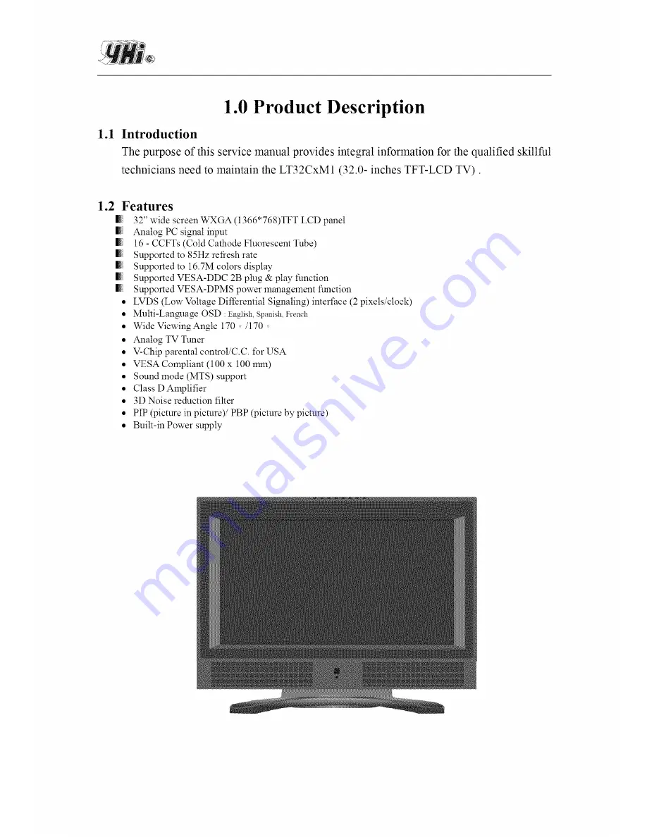
Page 4: ...t Tube Supported to 85Hz refresh rate Supported to 16 7M colors display Supported VESA DDC 2B plug play function Supported VESA DPMS power managelnent function LVDS Low Voltage Differential Signaling...

Page 5: ...ode Normally Black Viewing Angle Horizontal 170 degrees typical Degree Vertical 170 degrees typical Separate sync TTL level Horizontal sync Positive Negative Graphic VGA Vertical sync Positive Negativ...

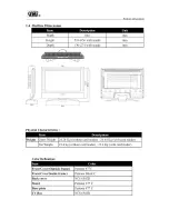
Page 6: ...111111 111111 Physical Characteristics Weight Gross Weight 24 24 Kg without card reader 24 44 Kg with card reader Net Weight 19 4 kg without card reader 19 6 Kg with card reader Color Defination Front...

Page 7: ...clock Screen Size 31 51 Diagonal inch Effective Display size 697 68 H x 392 26 V mm Pixel Number 1366 x R G B x 768 Pixels Color filter arrangement RGB vertical stripe Display Method Normally black Dr...

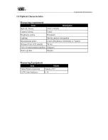
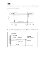
Page 8: ...rightness setting Lighting Measurement point Distance from LCD module View of measurement machine Warm up time 110 v 60 Hz Center Maximum Outside optical interception Center Brightness Uniformity is 5...

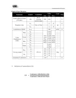
Page 9: ...Response time Luminance of White Red Chr C nlatricitY cIE _rl_e_ White Hor Ver Luminance Uniformity CR TFR TED LWH XR YR Xc_ Yc_ XB YB Xw Yw x X y y Ox O Viewing normal angle Gray to Gray CR 10 O Def...

Page 10: ...d as the following figure A y _i_h Any darker gray level T rl_ TrR fightergray level IJ Surface Luminance is a measurement of the active display area 50 cm from the center of the surface in condition...

Page 11: ...ertical y axis with respect to the z axis which is normal to the LCD surface Normal 0x 0y 0 0X 90 X 0y 0y 12 o clock direction Oy 90 6 o clock Y x 0X 90 0y 90 Definition of luminance uniformity 8W 5 p...

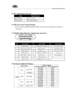
Page 12: ...4 D Sub Analog Input Electrical Properties Analog R G B Signal level Separate sync Horizontal sync Vertical sync 0 7 Vp_p 75 ohm 4 5 TTL level Positive Negative Positive Negative D sub Pin Assignment...

Page 13: ...0 Shield 9 TMDS DATA 0 16 10 TMDS Clock 17 11 TMDS Clock Shield 18 12 TMDS Clock 19 13 CEC not used 14 RESERVED N C on device SCL DDC Clock SDA DDC SAra DDC CEC Ground 5V Power Hot Plug Detect 2 8 Ana...

Page 14: ...32W max 80 MIN AT FULL LOAD C V MODE NOMINAL LINE 110V 220V MEASURED AFTER 30MINUTES FULL LOAD BURN IN VESA DPMS Signaling ON Mode 232 W max ACTIVE OFF 5W ON Mode N A ACTIVE OFF 3 sec 2 10 Power Manag...

Page 15: ...imension Functions OSD Operation Outside dimension 1005 W 772 H 305 D mm 42 997 SO0 _ 29_ C _9 FCC Label Model Number LT32C1Pl h _ ut AC _00 240V 50 60Hz 3 5A _ s_fact_r_g ONe J SIN I I I I J 1 This d...

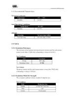
Page 16: ...ween the power terminal and the earth ground contact is more than 10 MR while withstanding a voltage of 3kV DC Test Conditions Voltage 3k V dc Resistance Value 10 M_ Test Criteria The power terminal a...

Page 17: ...ng a 2 6kVac and 2 6k ac for duration of lnaxilnum 3 sec between the metallic chassis and the input power supply active and neutral terminals connected together 2 13 Regulatory Standards 2 13 1 Safety...

Page 18: ...ower Power on off 2 Source Source select Menu Get into OSD t _r PC TV mode CH Select channel CH Select channel VOL I_ Control volume VOL _ Control volume Enter Exit fiom OSD Enter to sub menu LED indi...

Page 19: ...eo output device Sonnects the sub woofer audio in _ ideo output terminal connecting to the input terminal of the video input device The video output sources are AVI AV2 AV3 and TV _udio output termina...

Page 20: ...9 Sleep Set the Timer to turn off the set 10 Recall Back to previous channel 11 CATV Enter into the channel after you select channel by number 12 Number Keys Select channel by nmnber 1 12 13 MENU Get...

Page 21: ...D menu Use CHv CHA to scroll the options on the menu 2 Press Enter to submenus 3 Use 4 D to adjust the settings 4 Press Enter to confirm the setting 5 Press Menu to exit the current OSD page 3 4 PIP S...

Page 22: ...4 0 System descriptions 4 1 System block diagram 1 System description BLOCK D_GRAM I_SC 22...

Page 23: ...System description 4 2 System Block Diagram 2 Audio Processor NTSC iiiiii iiiiiiii ii_ii_ i iiii_ i ii i_iiiii i_iiiii ii ii ii ii ii ii ii i 23...

Page 24: ...Power board J6 To Inverter board CNS To IR board J8 To Power board I CN1 To Key Pad I J3 To RCA board System description JP7 To Speaker J1 To Card reader Option J5 To DVD Option CN7 To Video board J2...

Page 25: ...System description 4 3 3 Power board To Inverter board To Main board J4 To Main board J8 I To AC input socket I 4 3 4 Front RCA board To Video board CN2 I I I To Main board 13 I 25...

Page 26: ...ard To Main board CN1 4 4 Pin Configuration CN1 To Key board Connector 1 NC 2 3 3 V 3 NC 4 VIN2 5 ADC2_return 6 ADC VRFE 7 ADC1 return 8 Vinl 9 NC 10 Ground CN5 To IR board Connector 1 Ground 2 5v 3 I...

Page 27: ...2 CARD IR 3 Ground J2 To Video board CN2 Connector Component 2 1 PR out 2 Ground 3 PY out 4 Ground 5 PB out 6 Ground 7 Ground J3 To Earphone Connector 1 Ground 2 L OUT 3 Mode 4 R OUT J4 To Power board...

Page 28: ...DVD_IR 4 Ground J6 To Inverter Connector 1 2 3 1NV ON OFF ON OFF Control BLACK LIGHT Brightness Control Ground J7 To S _eaker 1 Speaker L 2 Speaker R 3 NC 4 NC 5 Speaker L 6 Speaker R J8 To Power boa...

Page 29: ...14 15 16 17 18 5V 5V 5V 5V TXA0 TXA0 TXAI TXA1 TXA2 TXA2 Ground Ground TXAC TXAC Ground Ground TXA3 TXA3 19 20 21 22 23 24 25 26 27 28 29 30 31 32 33 34 35 36 Ground Ground TXB0 TXB0 TXBI TXB 1 TXB2...

Page 30: ...1 Explore Diagram 5 2 Removal and Replacement 5 2 1 Remove and Replace Stand 1 Remove Screw PN 066 00581 00 Reverse procedure for Replacement 5 2 2 Remove and Replace Video board 1 Remove Screws P _ _...

Page 31: ...System description 1 Remove Screw PiN 066 00844 00 2 Remove Screw PiN 066 00610 00 1 Remove Screw PN 066 00615 00 2 Remove Screw PiN 066 00669 00 Remove Screw P N 066 00578 00 31...

Page 32: ...System description Relnove Screw PN 066 00742 00 Remove Screw PN 066 00742 00 Remove Screw I P N 066 00850 00 Remove Screw PiN 066 00742 00 Remove the rear cover after removing all the above screws I...

Page 33: ...cription 1 Remove Screws PN 066 00610 00 For Card Reader 5 2 5 Remove and Replace Main board 2 Remove Screws PN 066 00610 00 For front RCA board Reverse procedure for Replacement 1 Remove the connecto...

Page 34: ...System description Remove Screw P N 066 00614 00 Remove Screw P N 066 00578 00 I Reverse procedure for Replacement 34...

Page 35: ...6 Remove and Replace Power board System description 1 Remove Screws P N 066 00614 00 I 2 Remove the connectors 3 Remove Screws P N 066 006577 00 Reverse procedure for Replacement I 35 6 Remove Screws...

Page 36: ...5 2 7 Remove and Replace Panel 1 Remove Screw P N 066 00575 00 and take the panel ass y fiom fiont bezel System description 36...

Page 37: ...System description 1 Remove Inverter connecting wire 2 Remove Panel connecting wire I 3 Remove Screw P N 066 00849 00 Reverse procedure for Replacement 37...

Page 38: ...pply voltage for inverter 24Vdc 2 Check Inverter 3 Check J6 main board to Inverter connecting wire 4 Check Main board 1 CheckVLCD 5Von J9 connector 2 Check Panel connector 3 Check connecting wire J9 t...

Page 39: ...ption Item Symptom Inspection points 8 Can t receive TVorCable 1 Check Video board program 9 Card Reader problem 1 Check J1 Main board toCard Reader connecting wire Option 2 Check Card Reader 3 Check...

Page 40: ...Part Name BATTERY LABEL Protron PLTV 32M BARCODELABEL _ _ CARTON LABEL Prosonic LABEL FOR HDMI LOGO gg_g _ PLTV 30 PLTV 27 _I _ Protron PLTV 32M _ _a R 1 PE CUSHION CUSHION _ _ EPE _SL _ _ Protron _2...

Page 41: ...me BRACKET PANEL SIDE AU BRACKET TV BD IO AV BRACKET STAND NECK BRACKET MAIN BD IO HDMI BRACKET TV BD IO TV2 BRACKET TV BD BRACKET MAIN BD CASE TV COVER TOP AV _p_q CASE TV COVER BOTTOM R1 CASE FRONT...

Page 42: ...ZINC 8 PCS MYLAR CARD READER LT32C 1P1 1 PCS _g _ _ ga 13 PCS _ _g g Meet Rohs 2 PCS g_ g g 2 PCS BUTTON 1 PCS SPRING 8 PCS HOLDER DIE CASTING 1 PCS PANEL Meet Rohs 1 PCS LENS IR _g_ LT32C 1P 1 1 PCS...

Page 43: ...n Item Part No 88 971 10616 00 89 971 1031C 00000 90 971 10579 01 Part Name DIP PCBA K B DIP PCBA IR LED BOARD DIP FRONT RCA BOARD REV E Q D Unit 1 SET 1 SET 1 SET Location Approved by Jerry Prepared...

Reviews: