
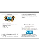
1. Turn on the power switch
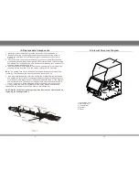
2. Press CH3 button for 3 seconds and the display below will be shown. If no
operation is carried out for 12 seconds, the original setting will be retained and
the rework station is returned to settings mode.
3. Press temperature/data plus-minus button to switch between Fahrenheit or
Celsius temperature display mode, and press CH3 to confirm. The setting will
be automatically saved and the rework station is returned to settings mode.
Switch between Fahrenheit/Celsius temperature display
5
6
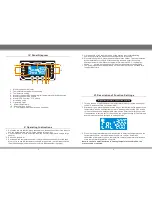
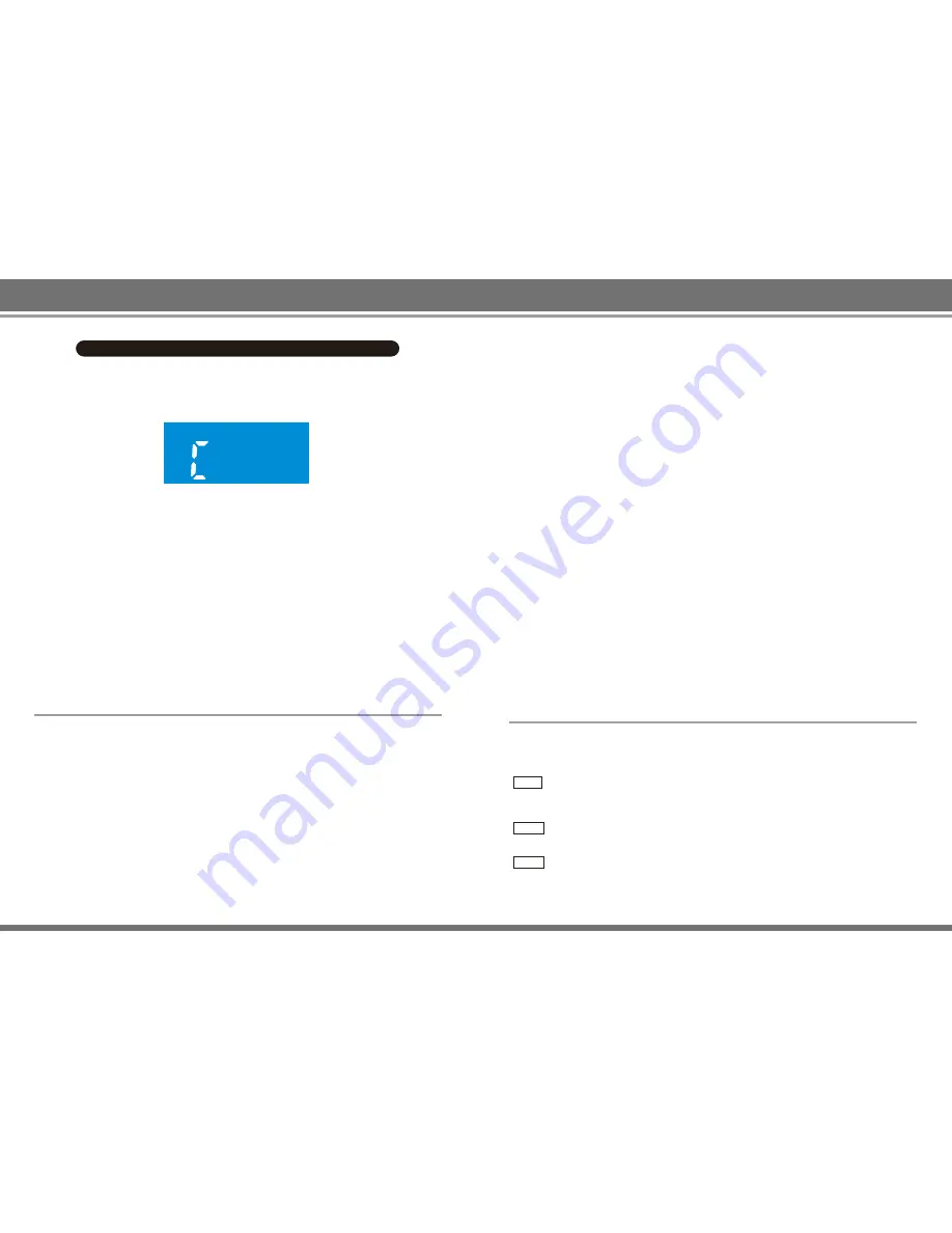
S-E Sensor Error:
If any part of the sensor or sensor circuit fails, the
temperature parameter window will display “S-E” to be conveyed to the
handle in order to cut off the electric current, after which the system will
stop working.
H-E Heated Element Error:
If the system cannot supply power to the heating
element of the handle, the temperature parameter window will display the “
H-E” symbol, which means the heating core may already be damaged.
ERR Motor Error:
If any part of the motor or electric circuit fails, the air volume
parameter window will display the "ERR" symbol, to be conveyed to the
motor in order to cut off the electric current, after which the system will stop
working.
8. Do not touch the heat pipe or directly spray someone's face with hot air, as
there is a risk of burning the human body. When it is just started, white smoke
may be emitted - this is a normal occurrence, which will later disappear.
9. When replacing the heating element, be careful not to damage the ground
wire.
10. During replacement, pay attention to the order and color of the connection
cable. Never make a mistake in the connection!
11. Please replace with the same model of heating element or heating core.
Special Note:
Hello, dear user! Because the machine air gun and the soldering iron handle use
high-strength stainless steel tube, in the production process the machine must go
through inspection or calibration four times under normal working conditions. The
cylinder will turn slightly yellow due to high temperature. When the new machine
is disassembled or used, and slight yellowing is discovered around the steel
cylinder, this is to be regarded as normal occurrence, so please remain at ease
when using it!
When a problem occurs with the equipment, the system will display a variety of
error symbols and an alarm sound will be emitted until the system power is cut off.
If the following symbols are displayed, please follow the prompts to troubleshoot
them.
VIII. Error Symbols
VII. Terms of Use
1. When turning on the power supply air gun, the handle must be placed on the
handle holder.
2. Please keep the air vent open and free of obstructions.
3. After completion of work, the heating handle must be placed on the handle
holder. Let the machine cool down by itself until it displays “---” (stop air
supply) to be able to turn off the air gun power switch.
4. When using a smaller nozzle other than the standard machine nozzle, you
must adjust the air flow to the max and to use lower temperatures within a
short period of time. Avoid long-term use of the air gun as it causes damage.
5. In accordance with work needs, choose the right air nozzle. Different air
nozzles may have slightly different temperatures. The distance between the
outlet and the object is at least 2 mm.
6. Do not forcefully install the nozzle or use pliers to pull the nozzle edge. Do not
tighten the screw firmly.
7. Before installing the nozzle, both the heat pipe and the nozzle must be cooled
first.


