1. Heating element replacement must be done after it has cooled down.
2. Remove the spring on the original handle and unscrew the three screws
holding the steel tube. Pull out the steel pipe from the handle case (as in
Figure 1).
3. Cut off the cable tie on the outlet and unplug the sensor cable. Release the
grounded outlet and the grounding cable in the internal frame of the steel pipe
and handle. Pull out the heating core from the steel pipe and take out the steel
pipe and the damaged heating core.
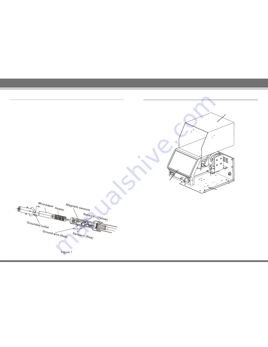
4. Insert the attached mica paper roll on the new heating core (must fittingly be
inserted into the steel tube, with the excess cut off) into the steel pipe.
Note:
The heating core sensor wire should be opposite the ground lead of the
steel pipe. The red and yellow heat shrink tube is the sensor wire.
5. Insert the installed heating core element into the internal frame of the handle
and tighten the set screw. (The heating element connector of the heating core
must be inserted in place) Connect all the cables well as shown in the diagram
and set the cable tie. The sensor wire has polarity, so please pay attention to
the color difference. Wires of the same color are connected to each other.
6. Finally, put on the external handle cover and fix the screws and springs (
reassemble the handle in the reverse order of its disassembly).
CAUTION: Be careful not to damage the ground wire on the steel pipe when
replacing the heating element.
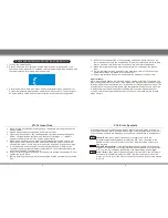
IX. Replaceable Components
9
10
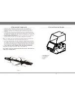
1. Machine Cover
2. Bottom Plate
3. Transformer
4. Blower
5. Panel
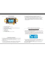
X. Internal Structure Diagram
1
2
3
4
5