48
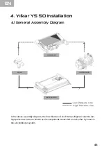
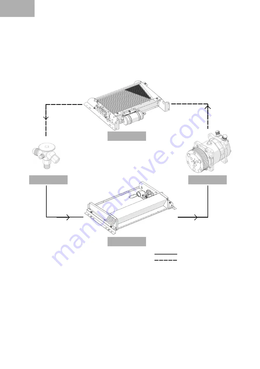
4.1 General Assembly Diagram
4. Yılkar YS 50 Installation
CONDENSER
VALVE
COMPRESSOR
EVAPORATOR
H gh Pressure L ne
Low Pressure L ne
In the above assembly diagram, the flow direction of the R134a refrigerant and the low-
high pressure zones are shown on the components connected to each other by hoses in
the air conditioner system.
EN
Summary of Contents for YS 50
Page 22: ...TR YS 50 DI N TES ST G R N S R Y N 16...
Page 24: ...18 YS 50 N TES ALT G R N S R Y N TR...
Page 38: ...YS 50 ST VE ALT N TES SON G R N S R Y N 32 S R Y N ST G R N ALT G R N TR...
Page 45: ......
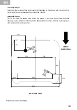
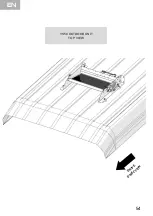
Page 61: ...YS 50 OUTDOOR UNIT TOP VIEW 54 DRIVE DIRECTIO N EN...
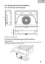
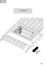
Page 63: ...YS 50 INDOOR UNIT TOP VIEW DRIVE DIRECTIO N EN 56...
Page 84: ......
Page 85: ......
Page 86: ......
Page 87: ......

