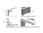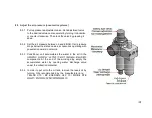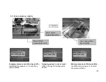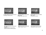
7.2.3 Put the boiled profile on the plate and justify it properly on the switches (PICTURE 4 NO.58) on set-square
(PICTURE 4 NO.26). Clamp will automatically fix the profile.
7.2.4 The machine will carry out the cleaning operation and stop.
NOTE: Press emergency button at the moment of potential danger
The milling cutters have to be started freely, without touching the profile. They have to start to
rotate first before making the milling operation.
8. MAINTENANCE, SERVICE AND REPAIR
8.1 Maintenance
8.1.1 Cut the electric and pneumatic power connections of the machine.
8.1.2 Clean all surfaces of the machine from burs, chips and foreign substances. If the machine will not be used for a
long time, lubricate undyed parts with oil that prevents rusting.
8.1.3 When cleaning the machine, do not use materials that may damage the dye.
8.1.4 Control cutting tools against corrosion, distortion and fractions. If cutting tools are damaged, change them..
8.1.5 Before using cutting tool, operate the machine out of gear and control whether it is inserted correctly, it is
without flexure and it is inserted appropriately. Do not use cutting tools that are damaged or lost its functionality.
8.1.6 If the sawteeth are blunted, change immediately with a new / sharpened saw.
8.1.7 Sharpen with proper sharpening machines by taking the angular value of the saw into consideration.,
Summary of Contents for CA 601
Page 4: ...BOYUTLAR DIMENSIONS FIGURE ...
Page 5: ... PART LIST FIGURE FIGURE ...
Page 6: ... FIGURE FIGURE ...
Page 7: ... FIGURE ...
Page 9: ...NO PART NO PICTURE STOK KODU CODE 1 1EL020000 0012 2 3 4 ...
Page 10: ...5 6 7 8 ...
Page 19: ......
Page 20: ......
Page 30: ...ELECTRIC PNEUMATIC ...
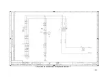
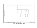
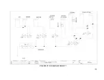
Page 31: ...3 PHASE ELECTRICAL DIAGRAM SHEET 1 ...
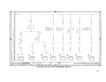
Page 32: ...3 PHASE ELECTRICAL DIAGRAM SHEET 2 ...
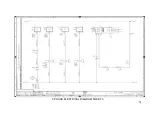
Page 33: ...3 PHASE ELECTRICAL DIAGRAM SHEET 3 ...
Page 34: ...3 PHASE ELECTRICAL DIAGRAM SHEET 4 ...
Page 35: ...PNEUMATIC DIAGRAM SHEET 1 ...


