46
7.2.2 KD 350-400 M/D: The clamping is manual. KD 350-400 P: Clamping is pneumatically
.
You can adjust forward-
backward, up-down position of the clamps with special clamping parts (FIGURE 1 NO.77/78). Control of
pneumatic clamp is made with the button (FIGURE 1 NO.71) on the chassis (FIGURE 1 NO.1).
7.2.3 Control the firmness of the special clamping screw (FIGURE 2 NO.89) on set square (FIGURE 1 NO.25)
7.2.4 Operate the motor by pressing the start button (FIGURE 1 NO.66-1) on arm (FIGURE 1 NO.66)
7.2.5 After cutting off the material, bring the cutting grip to its original position, press the Stop button. The saw blade
will come to a full stop after continuing its idle rotation for a while.
7.2.6 After cutting off the material, bring the cutting grip to its original position, press the Stop button. The saw blade
will come to a full stop after continuing its idle rotation for a while.
7.2.7 Remove the part by opening the clamps.
Don’t operate the saw while it touches the work piece. The saw must be operated only when the head
is in the top position.
7.3 Angular cutting
7.3.1 Loosen the special clamping screw (FIGURE 2 NO.89) on set square (FIGURE 1 NO.25)
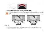
7.3.2 Pull the spring shaft (FIGURE 1 NO.23) from spring slot. At the same time, get the head (FIGURE 1 NO.33) at
the level you want with the aid of plastic arm (FIGURE 1 NO.64) with your other hand. You can read the angle
values with the aid of level reader (FIGURE 1 NO.17) on the plate (FIGURE 1 NO.33).
7.3.3 15- 22.5- 30 and 45 degrees can be set with the aid of spring (FIGURE 1 NO.23) and other sub degrees can be
set with the aid of special clamping screw (FIGURE 2 NO.89) on the set square (FIGURE 1 NO.25). The spring
Summary of Contents for KD 350 M
Page 4: ...4...
Page 5: ...5...
Page 6: ...6 ELEKTR K EMASI WIRING DIAGRAM KD 350 400 3P...
Page 7: ...7 KD 350 400 1P...
Page 8: ...8 PN MAT K EMASI PNEUMATIC DIAGRAM KD 350 400 P...
Page 9: ...9 KD 350 400 PS...
Page 10: ...10 KESME D YAGRAMI CUTTING DIAGRAM KD 350 M D P...
Page 11: ...11 KD 400 M D P...
Page 12: ...12 BOYUTLAR DIMENSIONS...
Page 13: ...13 PAR A L STES PART LIST RES M FIGURE 1...
Page 14: ...14 RES M FIGURE 2...
Page 53: ...53 1 1 1 1 2 2 2 1 2 2 2 3 3 4 5 5 1 5 2 6 7 7 1 7 2 7 3 8 8 1 8 2 8 3 8 4 8 5 9 10...
Page 54: ...54 1 1 1 1 2 YILMAZ 10...
Page 56: ...56 2 2 1...
Page 57: ...57 2 2 2 2 1 CE 2 2 2 2 2 3 2 2 4 2 2 5 2 3 2 3 1 2 3 2 2 3 3 2 3 4...
Page 58: ...58 2 3 5 2 3 6 2 3 7 2 3 8 2 3 9 2 3 10 2 3 11 2 3 12 2 3 13 2 3 14 2 3 15...
Page 61: ...61 5 2 5 2 1 5 2 2 5 2 3 5 2 4 230 50 400 50 5 2 5 B 5 2 6 6 6 1 6 2 6 3 6 4...
Page 62: ...62 6 5 6 6 6 7 7 7 1 7 1 1 7 1 2 7 1 3 7 1 4 2 NO 57 7 1 5 7 1 6...
Page 63: ...63 7 1 7 7 1 8 7 1 9...
Page 70: ...70 9 6 8...


