background image

37 


8.2  Changing the cutting tool 


8.2.1  Use 

protective gloves when replacing 

cutting tool. 


8.2.2  Cut the electric connection of the machine. 


8.2.3  Open the upper protection cover. (FIGURE 2-NO: 6) 


8.2.4  With the help of 6 Allen key (given with the machine), demount the bolt (FIGURE 10-NO: 43) from its location.. 

Take the washer (FIGURE 10 NO: 44) and the exterior coupling (FIGURE 10 NO: 45) to the outside.. Take the 
saw cutter group (FIGURE 10 NO:47) over the rotor shaft (FIGURE 10 NO: 48) by taking, replace it with a new 
group saws.. After replacing the saw cutters, do the opposite of the demounting procedure and tighten the bolt.  

(ON KM 213 MODELS)


8.2.5  Push the blade-changing button (FIGURE 6 / 9 NO: 25). Bearing tightening the saw group will go up (FIGURE 9 

NO: 41). Take the idle tightening bearing and take out the saw group. Mount the saw group, prepared according 
to  the  profile  to  be  processed,  on  the  shaft.  Push  the  blade-changing  button  again  and  mount  the  tightening 
bearing that you took off.

 (ON KM 215 MODELS)


WHEN  REPLACING  THE  MILLING  CUTTER  GROUP,  ENSURE  THE  CUTTERS  ROTATE  IN  THE 
CORRECT DIRECTION 
 

.  


Summary of Contents for KM 213

Page 1: ...Y İSTANBUL TÜRKİYE TELEFON 0216 312 28 28 PBX TELEFAX 0216 484 42 88 İMZA KAŞE ÜRÜNÜN CİNSİ ALÜMİNYUM ve PVC ORTAKAYIT ALIŞTIRMA FREZE MAKİNESİ MARKASI YILMAZ MODEL KODU KM 213 KM 215 BANDROL SERİ NO TESLİM TARİHİ GARANTİ SÜRESİ 1 YIL AZAMİ TAMİR SÜRESİ 30 İŞ GÜNÜ YETKİLİ SATICI FİRMA ADRES TELEFON TELEFAX İMZA KAŞE ...

Page 2: ...ELLİKLER TECHNICAL FEATURES ТЕХНИЧЕСКИЕ ОСОБЕННОСТИ kg kg KM 213 800 W 50 Hz 230 V AC P N PE 1200 W 50 Hz 400 V AC 3 P PE 3000 D dak RPM D max 160 d 30 mm 6 8 bar 14 Lt dak Lt min W 95 L 55 H 127 87 116 KM 215 90 119 ...

Page 3: ...3 ...

Page 4: ...4 BOYUTLAR DIMENSIONS РАЗМЕРЫ RESİM FIGURE РИСУНОК 1 ...

Page 5: ...5 PARÇA LİSTESİ PART LIST ПЕРЕЧЕНЬ ДЕТАЛЕЙ RESİM FIGURE РИСУНОК 2 RESİM FIGURE РИСУНОК 3 1 5 7 3 4 2 6 8 9 11 10 12 14 13 18 19 16 17 15 ...

Page 6: ...6 20 RESİM FIGURE РИСУНОК 4 24 22 23 21 RESİM FIGURE РИСУНОК 5 25 27 26 28 29 RESİM FIGURE РИСУНОК 6 ...

Page 7: ...7 RESİM FIGURE РИСУНОК 8 32 34 31 30 33 40 38 37 35 39 36 RESİM FIGURE РИСУНОК 7 RESİM FIGURE РИСУНОК 8 ...

Page 8: ...8 49 50 51 53 52 RESİM FIGURE РИСУНОК 9 RESİM FIGURE РИСУНОК 10 RESİM FIGURE РИСУНОК 11 25 41 43 44 45 48 47 46 ...

Page 9: ...0002 1 2 1SC170000 0007 2 19 2TU011110 0091 1 3 1SA020000 0003 1 20 1PL010000 0020 1 4 1PN080000 0009 1 21 2TU011441 0017 1 5 2ET022441 0025 1 24 1ET052400 0016 1 6 1SA030000 0027 1 25 1PN010000 0010 1 7 1PN070000 0012 1 26 2TU011110 0552 1 8 2TU012510 0300 1 27 2TU011110 1172 1 9 2TU012610 0033 1 28 2TU011441 0171 1 10 2TU012610 0034 1 29 1PN010000 0012 1 11 2TU012510 0282 1 30 1PN020000 0089 1 1...

Page 10: ... КОД PARÇA ADI PART NAME НАИМЕНОВАНИЕ ДЕТАЛИ 26 2TU011110 0552 TESTERE BIÇAĞI MALAFASI SAW BLADE SHAFT 16 2TU012610 0010 MENGENE YATAĞI CLAMP MOUNTING BRACKET 17 3UA060030 0004 PNÖMATİK MENGENE PNEUMATIC CLAMP 17 1 1PL010000 0033 MENGENE PABUCU CLAMP FEET 29 1PN010000 0012 KD 350 400 PS SPRAYER SU PÜSKÜRTME VALF WATER SPRAY VALVE ...

Page 11: ...11 30 1PN020000 0089 PİSTON PISTON 31 3UA050030 0014 HİDROÇEK ÜNİTESİ HYDROCONTROL UNIT 1EL020000 0016 KAPAK SWİTCH COVER SWITCH ...

Page 12: ...3 General Safety Information 3 Machine s Description 4 Transport of the Machine 5 Installation of the Machine 5 1 Preparation 5 2 Connecting to Power Source 6 Machine s Safety Information 7 Operation 7 1 Preparation 7 2 Operation 8 Maintenance Service and Repair 8 1 Maintenance 8 2 Changing the cutting tool 8 3 Adjust the air pressure 9 Warranty conditions ...

Page 13: ...drawings and details contained in this manual constitute a guide for the operator 1 2 Service Information In case of any technical problem please contact your nearest YILMAZ dealer or YILMAZ head office through the above mentioned phone fax or e mail address Technical labels with the model description of the machine are fixed onto the front side of each machine The machine s serial number and manu...

Page 14: ...e com tr Web www yilmazmachine com tr For minimize the documantation It is wery necessary to mention below details at the agreements signed with suppliers and dealers of the purchased machines Machine model Voltage and frequency Machine s serial number Date of purchase Description of the machine fault Name of dealer where machine was purchased Average daily operation period ...

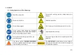
Page 15: ...ld be damaged during operation don t touch and unplug it Never use damaged power cables High temperature warning During saw blade change operations use protective gloves Keep your fingers clear of the movable parts of the glide arm The above symbol DANGER WARNING warns you against specific dangers and you have definitely to read them The IMPORTANT symbol above is one telling to apply special care ...

Page 16: ...nts of this manual 2 2 5 All directives recommendations and general safety rules contained in this manual have to be observed fully The machine cannot be operated in any way for purposes other than those described herein Otherwise the manufacturer shall not be deemed responsible for any damages or injuries And such circumstances would lead to the termination of the warranty 2 3 General Safety Info...

Page 17: ...3 9 Unplug first before conducting and maintenance works 2 3 10 Ensure that any keys or adjustment tools have been removed before operating the machine 2 3 11 If you are required to operate the machine outside use only appropriate extension cables 2 3 12 Repairs should be carried out by qualified technicians only Otherwise accidents may occur 2 3 13 Before starting a new operation check the approp...

Page 18: ...ce keys Milling cutter set Angular clamping Spray cooling system Air gun User s manual 4 TRANSPORT OF THE MACHINE 4 1 The transport should be done by qualified personnel only 4 2 The machine should be transported by lifting with proper equipment not touching the ground during the transport 4 3 Unless customer requests the contrary the machine will be delivered with wooden packaging 4 4 Movable par...

Page 19: ...URE 2 NO 2 in the bottom part 5 2 Connecting to Power Source 5 2 1 The Electrical connection must be made by a licensed electrician 5 2 2 The power outlet socket on the machine should be available 5 2 3 Plug the machine to a grounded socket 5 2 4 Main voltage of the machine is optional as 230 V 50 Hz or 400 V 50 Hz 5 2 5 Check the power source voltage It has to be in accordance with the values sti...

Page 20: ...fective safety devices or faulty parts 6 5 Never replace the milling cutters before unplugging first 6 6 Keep foreign materials away from the working area of the machine keep away from the machine s moving parts 6 7 Do not work on the machine by removing the protective parts The safety data have been defined above In order to prevent physical damage or damage to the equipment please read the safet...

Page 21: ...his product has 4 pieces of leaning screws The mechanism holding screws is turnable FIGURE 8 By rotating the mechanism desired leaning screw can be adjusted 7 2 3 By pushing the clamp button FIGURE 11 NO 53 with the help of two clamps on the machine FIGURE 3 NO 12 17 fix the profile which was touched to the edge of the support 7 2 4 This machine has angled milling process For this process loosen t...

Page 22: ...ections of the machine 8 1 2 Clean all surfaces of the machine from burs chips and foreign substances If the machine will not be used for a long time lubricate undyed parts with oil that prevents rusting 8 1 3 When cleaning the machine do not use materials that may damage the dye 8 1 4 Control cutting tools against corrosion distortion and fractions If cutting tools are damaged change them 8 1 5 B...

Page 23: ...e rotor shaft FIGURE 10 NO 48 by taking replace it with a new group saws After replacing the saw cutters do the opposite of the demounting procedure and tighten the bolt ON KM 213 MODELS 8 2 5 Push the blade changing button FIGURE 6 9 NO 25 Bearing tightening the saw group will go up FIGURE 9 NO 41 Take the idle tightening bearing and take out the saw group Mount the saw group prepared according t...

Page 24: ...he stated values accessories operating with pneumatic power do not work 8 3 3 Conditioner unit accumulates the water in the air in the collection container so that it won t damage pneumatic components At the end of the working day empty the accumulated water by opening water discharge valve under the collection container 8 3 4 In order to put oil to the oil tank remove the reservoir by turning Oil...

Reviews: