43
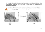
7.1.7 Adjust the reducer speed adjustment screw (See Figure-11) by rotating in the direction of clockwise until
providing the desired progress if the saw group cutting progress is fast. Make the opposite of the above action if the
saw group cutting progress is slow.
7.1.8 According to the type and shape of the material to be cut it can be adjusted by controlling the clamp speed.
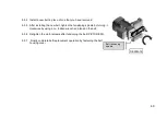
Ensure that the pneumatıc clamps are outsıde the cuttıng range of the saw blade after adjustıng the
desıred angle
. (PICTURE 12)
FIGURE-12
Summary of Contents for SC 550P
Page 4: ...4 BOYUTLAR DIMENSIONS РАЗМЕРЫ RESİM FIGURE РИСУНОК 1 ...
Page 5: ...5 KESME DİYAGRAMI CUTTING DIAGRAM ДИАГРАММА РЕЗКИ ...
Page 34: ...73 ELECTRIC PNEUMATIC DİAGRAM ...
Page 35: ...74 3P ELECTRICAL DIAGRAM SHEET 1 ...
Page 36: ...75 3P ELECTRICAL DIAGRAM SHEET 2 ...
Page 37: ...76 3P ELECTRICAL DIAGRAM SHEET 3 ...
Page 38: ...77 3P ELECTRICAL DIAGRAM SHEET 4 ...
Page 39: ...78 3P ELECTRICAL DIAGRAM SHEET 5 ...
Page 40: ...79 3P ELECTRICAL DIAGRAM SHEET 6 ...
Page 41: ...80 PNEUMATIC DIAGRAM ...


