YG125-30B
Maintenance Manual
Front wheel, front suspension device and steering stem
117
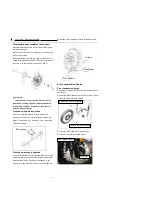
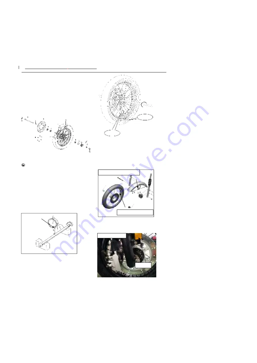
Disassembly and assembly of front wheel
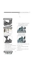
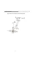
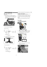
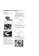
Disassemble and assemble the front wheel according to
the following diagam.
After the bearing is removed, replace with a new bearing
along with dust seal.
While assembling the brake disc, apply small amount of
thread retaining adhesive LOCTITE243 on the threads of
the screw, with tightening torque being 20-30N.m.
Warning
The brake disc retaining screw must be coated
with thread retaining adhesive, with the tightening
torque being 20-30N.m. Otherwise, it may cause a
personal safety accident.
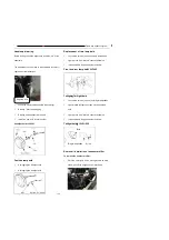
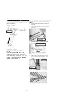
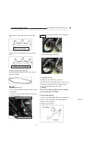
Front wheel spindle inspection
Place the front wheel spindle on the V-holder, and
measure the deflection of the wheel spindle with a dial
gauge; if the reading is no less than 0.2mm, replace the
front wheel spindle.
Front wheel bearing inspection
Place the front wheel on the calibration table, inspect the
rim
’
s deflection, and then manually rotate the wheel and
measure its deflection value with a dial gauge; if the
reading is no less than 2mm, replace the wheel bearing.
Front suspension device
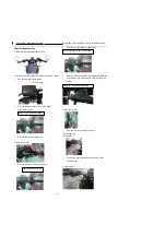
Front suspension device
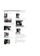
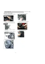
Removal of coverings) and front wheels (See Removal of
front wheel).
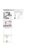
Remove the front mudguar and front license plate. Do not
scratch the outer decorating surface
Remove the front brake caliper and wire clip
Remove the wire clip and speed sensor
Dial indicator
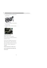
Remove the front wheels
Remove the front mudguard
Front brake caliper
Wire clip
Dial indicator
Rotate it
Dial indicator
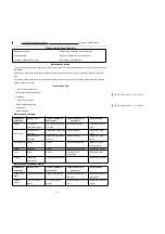
Summary of Contents for YG125-30B
Page 99: ...YG125 30B Maintenance Manual Frame and exhaust system 106 10 Frame and exhaust system...
Page 130: ...YG125 30B Maintenance Manual Illumination signal system 136 Circuit schematic drawing...
Page 141: ...YG125 30B Maintenance Manual Engine management system 147 Circuit schematic drawing...
Page 151: ...YG125 30B Maintenance Manual Electrical System Diagram 157 19 Electrical System Diagram...

