YG125-30B
Maintenance Manual
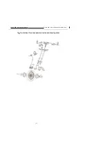
Front wheel, front suspension device and steering stem
120
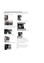
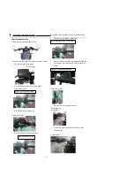
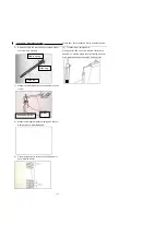
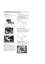
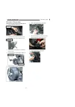
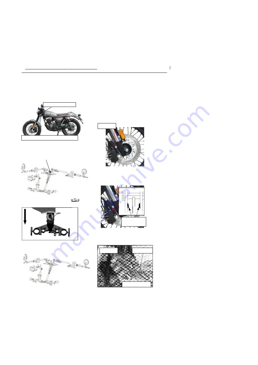
Removal of steering stem
Steering stem
1)
Park the motorcycle on the plane ground, and
remove front wheel, front fork and grip tube (control
subassembly) of the whole vehicle. Refer to the
related sections
2)
Remove the upper connect plate
3)
Use special socket for adjusting nut
Unscrew the adjusting nut.
4)
Lower steering stem
To mount of steering stem
Installation is in the reverse order of removal
While installing the steering stem, adjust the adjusting nut
and inspect it by turning it left and right and moving it up
and down to ensure no vertical play and flexible rotating
laterally.
Tighten the cap nut to the required torque of 60-70N.m.
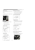
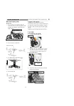
Front brake
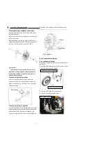
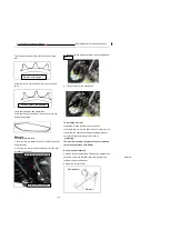
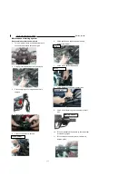
Front brake caliper inspection
1)
Dismantle front brake caliper bolt
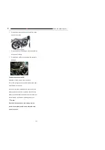
2)
Operating brake, if the wears limit line of the brake
shoe touch to the side of the brake disc. It shows
that the brake shoe has touched the wear limit.
Replace the brake shores.
3)
Take off front brake caliper and check brake shoe
whether exceed limit value
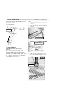
Adjusting Nut
Brake shoe
Spring compression
Hitch pin
Bolt
Remove the front wheels and front fork
Control subassembly
Upper connect plate
Cotouts
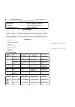
Summary of Contents for YG125-30B
Page 99: ...YG125 30B Maintenance Manual Frame and exhaust system 106 10 Frame and exhaust system...
Page 130: ...YG125 30B Maintenance Manual Illumination signal system 136 Circuit schematic drawing...
Page 141: ...YG125 30B Maintenance Manual Engine management system 147 Circuit schematic drawing...
Page 151: ...YG125 30B Maintenance Manual Electrical System Diagram 157 19 Electrical System Diagram...

