77
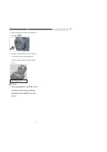
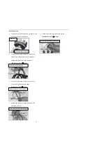
damage will occur.
Explanation:
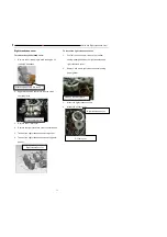
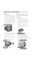
While unscrewing bolt, do it in a crossing way twice or thrice. Do in the same way for screwing up bolt.
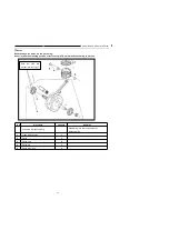
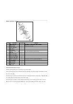
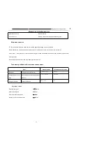
No
Procedure
Quantity
Remarks
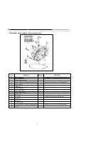
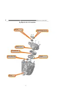
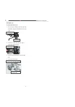
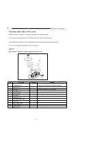
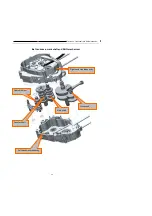
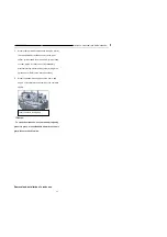
Removing order
Installation is in the reverse order of removal
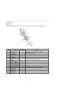
1
clutch bush
1
Tightening torque 12N.m.
2
clutch assembly
1
3
Nut M14*1
1
4
Flat washer
1
5
Deep
groove
ball
bearing
1
Gum base, soaking oil while assembling
6
Clutch out cover
1
7
Clutch lug washer
1
8
Clutch center bush
1
9
Clutch friction plate
5
10
clutch driven plate
4
Assemble with the sub stage side facing inwards
11
Clutch platen
1
12
Clutch spring
4
13
Clutch plate
1
14
Bolt m6*25
4
Summary of Contents for YG125-30B
Page 99: ...YG125 30B Maintenance Manual Frame and exhaust system 106 10 Frame and exhaust system...
Page 130: ...YG125 30B Maintenance Manual Illumination signal system 136 Circuit schematic drawing...
Page 141: ...YG125 30B Maintenance Manual Engine management system 147 Circuit schematic drawing...
Page 151: ...YG125 30B Maintenance Manual Electrical System Diagram 157 19 Electrical System Diagram...


