YG125-30B Maintenance Manual
Crankcase, crankshaft and Shift mechanism
89
Crankcase, crankshaft and Shift mechanism
Maintenance notice
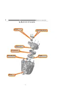
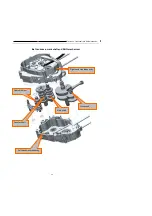
Crankshaft and balance shaft
Troubleshooting
Variable transmission system
Crankcase
Maintenance notice
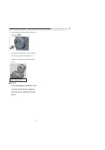
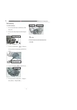
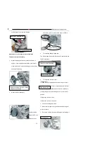
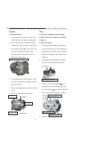
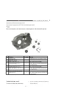
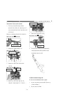
To carry out the maintenance stated herein, the engine must be removed from the frame.
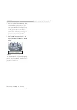
To repair the crankshaft, balance shaft or variable transmission system, the left hand crankcase and the right hand
crankcase must be separated, which is known as crankcase dissection. Before crankcase dissecting, the following parts
and components of the engine shall be removed:
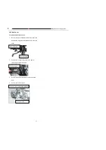
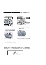
1 Right hand crankcase, clutch, gear shifter
2 Cylinder head cover, camshaft, cylinder head, cylinder and piston (See
“
Cylinder head, cylinder and piston
”
);
3 Left front cover, rotor assembly, electrical starting transmission system (See
“
Magneto and electrical starting
system
”
);
4 Driving drive sprocket, shift switch.
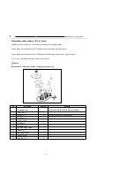
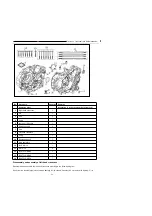
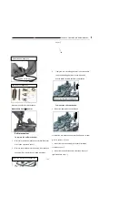
Before assembling, clean all parts and components with cleaning agent and dry them with compressed air.
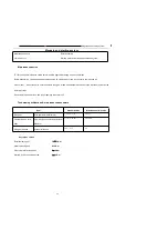
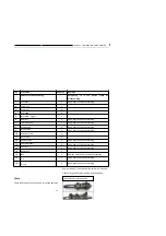
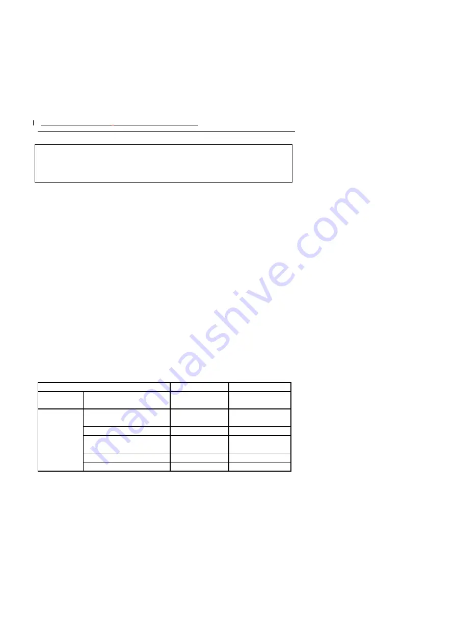
Technical specifications & maintenance benchmark
Item
Standard value
Maintenance limit value
Shift fork claw
thickness
Gear shift fork
6.05
~
5.40
5.80
Crankshaft
Connecting rod small end bore
diameter
Ф
20.03
~Ф
20.038
Ф
20.063
Disc planeness
0.028
~
0.042
0.06
Connecting rod big end radial
clearance
0.30
~
0.60
0.80
Radial runout
0.03
0.10
Left crank journal
Ф
29.959
~Ф
29.98
Ф
29.87
Summary of Contents for YG125-30B
Page 99: ...YG125 30B Maintenance Manual Frame and exhaust system 106 10 Frame and exhaust system...
Page 130: ...YG125 30B Maintenance Manual Illumination signal system 136 Circuit schematic drawing...
Page 141: ...YG125 30B Maintenance Manual Engine management system 147 Circuit schematic drawing...
Page 151: ...YG125 30B Maintenance Manual Electrical System Diagram 157 19 Electrical System Diagram...

