YG125-30B Maintenance Manual
Crankcase, crankshaft and Shift mechanism
101
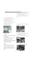
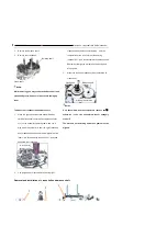
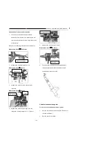
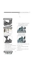
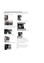
3.
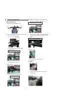
Remove the gearshift drum.
4.
Remove the shift fork.
5.
Remove the driving/driven shaft
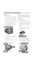
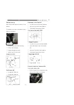
To mount the variable transmission system:
1.
Place the right hand crankcase assembled with
crankshaft and balance shaft on the assembly
operating table, and the driving/driven shaft and
assemble the them together.
2.
Assemble the shift fork with
3.
Mount the gearshift drum.
。
4.
Change the O-shaped sealing ring, mount the shift
fork, and check whether the driving/driven shaft can
rotate freely
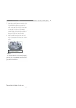
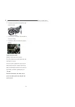
5.
Mount the shift arm
6.
Replace it with a new paper pad assembly one while
assembling
,
mount the left hand crankcase(See
“
Installation of crankcase")
Notice:
Only assemble when the temperature reaches 106
℃
,
otherwise it can
’
t be assembled. Never forcefully
strike it!
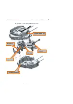
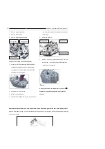
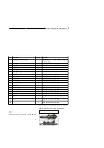
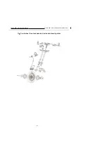
Removal and installation of driving shaft and driven shaft and gearshift drum and shifting shaft
Attention: the washer, retainer, etc. must be assembled in place at the correct positions, the spare parts 8 apply lubricating
oil. while assembling
Driving shaft
Counter shaft
Gearshift drum
Driving shaft
Counter shaft
Gearshift drum
Shift arm
Summary of Contents for YG125-30B
Page 99: ...YG125 30B Maintenance Manual Frame and exhaust system 106 10 Frame and exhaust system...
Page 130: ...YG125 30B Maintenance Manual Illumination signal system 136 Circuit schematic drawing...
Page 141: ...YG125 30B Maintenance Manual Engine management system 147 Circuit schematic drawing...
Page 151: ...YG125 30B Maintenance Manual Electrical System Diagram 157 19 Electrical System Diagram...

