YG48Q-5A Maintenance Manual
Inspection and adjustment
31
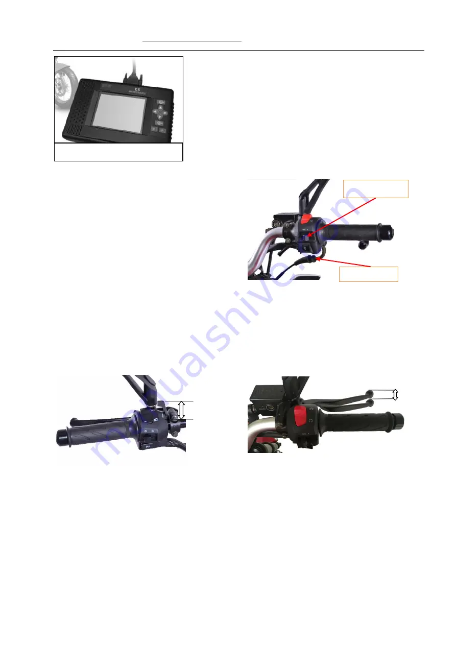
Throttle control
First, check whether the throttle control line is deformed,
twisted or damaged.
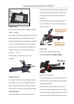
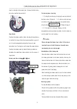
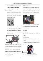
Then, measure the throttle bar free stroke. Turn the bar to
lean it against one side of the free stroke, and draw a
straight line between the bar and the balance weight with
a mark pen, and then turn the bar to lean it against the
other side of the free stroke; measure the distance the
straight line staggers, i.e. the throttle bar free stroke.
Free stroke
(
2-6
)
mm.
If the free stroke is insufficient or too big, make
adjustment.
Adjusting methods:
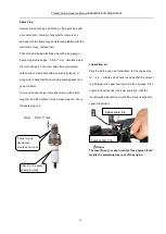
Fine adjustment: Pull open the rubber lagging, unscrew
the retaining nut A, and turn the adjusting solenoid to
adjust to a satisfied free stroke. And then screw up the
retaining nut A and mount the protective rubber lagging.
Coarse adjustment:
If the fine adjustment is not satisfying, separate the
throttle control line with throttle valve body and unscrew
the retaining nut B to make adjust the free stroke in a
larger range. Screw up the retaining but B after the
adjustment.
Check whether the throttle can turn smoothly from full
open to full close at any position. If there is clogging,
adjust or replace it.
Brake system
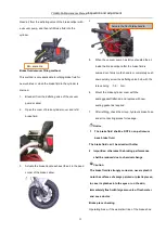
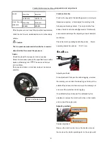
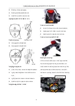
Check the front brake handle free stroke.
The brake handle free stroke
(
10-20
)
mm.
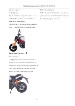
Brake fluid level inspection:
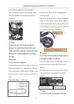
Check the brake fluid level in the front brake cylinder: if
the level is too low but not emptied, directly refill brake
fluid (DOT 4 brake fluid).
If the brake fluid inside the cylinder is found cloudy,
impure or smelt, Drain and refill the brake fluid. Refer to
the brake fluid vacuum filling method in the next section.
I If the brake fluid in both the front cylinders is drained,
(
10-20
)
mm
Maintaining & diagnostic instrument
Retaining nut B
Retaining nut A
(
2-6
)
m
m
Summary of Contents for YG48Q-5A
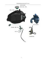
Page 38: ...YG48Q 5AMaintenance ManualFuel system 41 4 Fuel system...
Page 92: ...YG48Q 5AMaintenance ManualFrame and exhaust system 105 10 Frame and exhaust system...
Page 123: ...YG48Q 5A Maintenance ManualIllumination signal system 136 Circuit schematic drawing...
Page 126: ...YG48Q 5A Maintenance ManualIllumination signal system 139...
Page 133: ...YG48Q 5A Maintenance ManualEngine management system 146 Major parts and components...
Page 134: ...YG48Q 5A Maintenance ManualEngine management system 147...
Page 144: ...YG48Q 5A Maintenance ManualElectrical System Diagram 157 19 Electrical System Diagram...

