background image

YG48Q-5AMaintenance ManualCrankcase, crankshaft and Shift mechanism 


91 


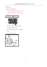
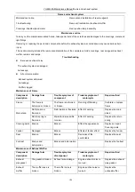
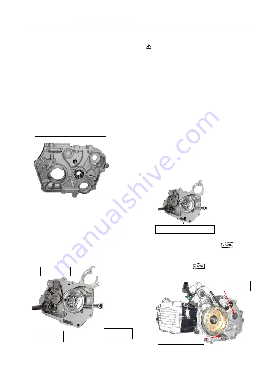
Crankcase


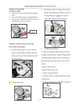
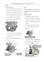
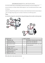
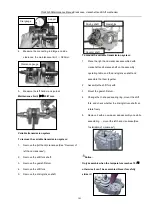
To remove the crankcase:


1. 

Remove the engine from the frame (engine oil fully 

drained) and put it on the assembly operating table. 

2. 

Remove such parts and components as right hand 

crankcase cover, clutch, gear shifter, cylinder head 

cover, camshaft, cylinder head, cylinder, piston, left 

front cover, rotor assembly, electrical starting 

transmission system, driving drive sprocket, etc. 

(Refer to the related sections). 


3. 

Use a Bakelite hammer or a nylon hammer to strike 

the left hand crankcase gently to separate it with the 

right hand crankcase. 

4. 

Remove the driving/driven shaft, gearshift drum, shift 

fork, etc. 

5. 

Remove the cranks-haft


Notice


Do not pry the left/right hand crankcase body by 

inserting such tools as screwdrivers into the mould 

closing face.


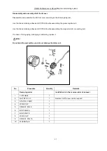
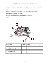
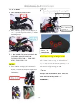
To mount the crankcase: 

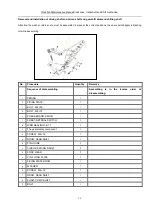
1. 

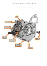
Place the right hand crankcase on the assembly 

operating table, and assemble the internal parts and 

components of the crankcase, including crankshaft, 

balance shaft, driving/driven shaft, gearshift drum, 

shift fork, etc. 

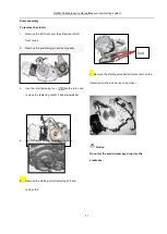
2. 

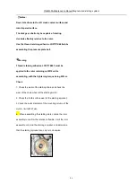
Clean up the left and right crankcase box surface, 

put the new crankcase paper pad, confirm the 

positioning pin. 


3. 

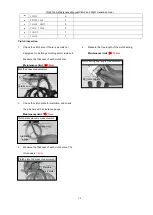
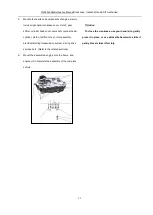
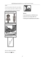
Use the counter shaft oil seal guide    to protect the 

counter shaft oil seal, use the gearshift drum oil seal 

guide    to protect the gearshift drum oil seal, and 

mount the left hand crankcase (closing). 


4. 

Mount the mould closing bolt and fasten it. 

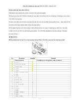
Balance shaft


Gearshift 

drum 


Crankshaft box paper pad 

Driving shaft 


Counter shaft 


Cranks-haft


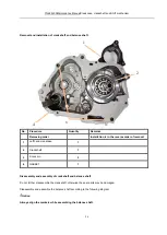
Remove the mould closing bolt 

Counter shaft oil seal


Shifting arm oil seal 


Summary of Contents for YG48Q-5A

Page 1: ...escribes various constituting parts of the motorcycle respectively Chapter 19 contains the electrical system diagram The standard maintenance procedures maintenance precautions and general maintenance...

Page 2: ...stem 79 87 9 Crankcase crankshaft and Shift mechanism 88 104 10 Frame and exhaust system 105 109 11 Front wheel front overhang and steering stem 110 121 12 Rear wheel and rear overhang 122 127 13 Gene...

Page 3: ...ion Bar Tool About Motorcycle Maintenance Maintenance Period Table Technical Data of Main Performance Symbol Descriptions Standard Torque Values Engine Number Position Photo of Complete Vehicle Frame...

Page 4: ...d components After reassembling check whether all the spare parts are mounted properly by means of turning moving and operating them 4 To disassemble and assemble a motorcycle special service tools SS...

Page 5: ...the terminals are not too long or are falling off The connector shall be fully inserted in place For a connector with lock confirm whether the lock is completely fixed Make sure the harness is not fal...

Page 6: ...ire harness shall not be slackened or be forcibly pulled If the wire harness has to contact the edge or sharp corner parts the contacting part shall be protected with hose or adhesive tape In case of...

Page 7: ...components 17 In case of rust on the terminals carry out connection operation after disposing it with abrasive paper etc 18 Do not forcibly twist or forcefully bend the cable Because a deformed or da...

Page 8: ...120 70 12 120 70 12 Normally loaded 225kPa Normally loaded 225kPa Single disc type Model 220 Single disc type Model 190 11L 92 Engine Mode Cylinder bore Stroke Cylinder displacement Compression ratio...

Page 9: ...d back type Sequence I N Electrical system Electric generator Accumulator capacity Power supply system Fusible cutout Spark plug Spark plug gap Ignition coil type Fuel supply mode Ignition mode Igniti...

Page 10: ...6 8 12 LOCTITE 648 Stator leads pressure plate bolt 2 6 8 12 LOCTITE 648 Spark Plug 1 12 18 25 Pensioner plate fastening bolt 1 6 7 10 Vehicle body Item Quantity Thread diameter mm Torque value N m T...

Page 11: ...torized gun special power tool for mantling dismantling bolt and nut Pawl socket for mantling dismantling oil filtering element nut and clutch nut A and B bolt socket for mantling dismantling A and B...

Page 12: ...e the clearance of piston cylinder valve etc Micrometer to measure the dimensions of piston piston pin etc Dial gauge to measure the wheel bouncing cylinder inner diameter etc Cylinder barometer to me...

Page 13: ...t and bolt fastening I I I I Wheel tire I I I I Steering column bearing I I I I Steering backstay cable Inspect every 5000km driving and replace every 10000km driving Maintenance shall be carried out...

Page 14: ...general purpose tools Tightening torque of 50 N m Use suggested engine oil Use the mixtures of engine oil and molybdenum disulfide Use thread locker Use sealant Use lithium base grease 1 Measures to...

Page 15: ...its quality scale must reach Grade SG and its viscosity shall be selected according to the accompanying diagram depending upon region and air temperature changes While replacing lubricating oil fully...

Page 16: ...ram besides applying dedicated lubricating oil for chain to the driving chain apply lithium base grease to all other positions All lubricating oils not specified for use in this manual shall be ordina...

Page 17: ...YG48Q 5AMaintenance ManualLubrication system 15 Crankshaft oil through Camshaft oil through Oil pump FILTER OIL Oil outlet Oil injection port...

Page 18: ...oil of the specified trademark into the crankcase then insert the oil filter plug CAUTION Application of engine oil of poor quality will have an impact on the functional performance and life span of...

Page 19: ...l filter cover and screw up the bolt to the specified torque Notice Before the crankcase is refilled with fresh engine oil the engine oil filter must be cleaned Oil Pump In case of failure the oil pum...

Page 20: ...clutch and the primary driving gear from rotating loosen the nut to remove the clutch component 4 Remove the oil pump Steps for oil pump installation The installation procedures are the removal proced...

Page 21: ...completed CAUTION The clutch retaining nut must be screwed up to the specified tightening torque must be applied to prevent the nut from getting loose Disassembly and assembly of oil pump Disassemble...

Page 22: ...to the sense organs of human being The way is simple and easy to use it is used wide in motorcycle maintenance Testing examination method This way is a way that test the size of part and change of geo...

Page 23: ...rcycle according to the contents hereof before using it Technical specifications Throttle bar free stroke 1 3 mm Recommended spark plug A7RTC Spark plug gap 0 6 0 7 mm Valve clearance cold IN 0 05 mm...

Page 24: ...et is in good condition To mount the spark plug manually screw up the spark plug first and then tighten it with a socket wrench Put on the spark plug cap Lubricating oil Park the motorcycle on a flat...

Page 25: ...is abnormal should check electronic ignition high voltage coil charging on the generator and trigger coil etc After properly timing pull off the tensioner locking key and coat the mixture of engine o...

Page 26: ...ging sound Dah Dah it indicates insufficient tension of the chain tensioner replace it with a new one To replace the chain tensioner Unscrew the 2 M6 16 socket cap screw to remove the sealing washer a...

Page 27: ...on but rock arms will move apparently when flywheel rotate a small angle the flywheel is not in the compressing stroke but exhaust intake stroke In this case continuously turn the flywheelclockwise fo...

Page 28: ...led by an ECU Since the intake flow at idle speed has been properly adjusted upon delivery do not adjust the idle speed adjusting screw as desired In case the idle speed is unsteady zero or too high f...

Page 29: ...rotective rubber lagging Coarse adjustment If the fine adjustment is not satisfying separate the throttle control line with throttle valve body and unscrew the retaining nut B to make adjust the free...

Page 30: ...the handle or completely push down quickly screw the deflating valve bolt with the torque being 7 9 N m 6 Mount the brake cylinder cover with the sealinggasket flattened and replace with new sealing...

Page 31: ...eds to be changed Please go to the designated special maintenance station And it is better to use the parts from our company Caution Please change the brake shoe in time if it has been touched the wea...

Page 32: ...le transmission system should adjust it according to the following overhauling content The content is the free stroke of clutch control handle general is 10 20 mm some venial need adjust the adjusting...

Page 33: ...k the amount of movement of the lower chain Driving chain tension 10 20 mm If the chain is too loose or too tight make adjustment Adjusting methods Unscrew the rear wheel spindle nut and turn the adju...

Page 34: ...eter if it is less than 12V recharge it with a charge power supply Seriously corroded conductor connectors of the battery shall be replaced Installation of accumulator Installation is in the reverse o...

Page 35: ...installing the rear brake spring shall be reliably hooked with the pin hole on the rear brake lamp switch After replacement adjustment shall still be carried out to the rear brake lamp switch Replace...

Page 36: ...clockwise Install new bulb in opposite order as below Taillight bulb LED 12V 0 5 1W Front and rear lamp bulb Loosen the screws remove the lamp lampshade Lightly press bulb rotate in counter clockwise...

Page 37: ...up to the specified torques Rear suspension Forcibly press the rear end of the seat cushion with the rear suspension and check the rear fork spindle sleeve for abrasion or damage If it is damaged repl...

Page 38: ...YG48Q 5AMaintenance ManualFuel system 41 4 Fuel system...

Page 39: ...position of such sealing members as the O ring while removing various parts of the fuel system While reassembling always use new sealing members such as an O ring Technical specifications Throat open...

Page 40: ...teps The installation procedures are the removal procedures in reverse order While installing note that the wiring of the fuel pump control wire shall be in strict accordance with the wiring diagram A...

Page 41: ...d throttle body If you need to replace the new parts proceed under the instruction technician Maintenance of Air Cleaner Component description Damage form Trouble symptom ofmotorcycle Repair method Ai...

Page 42: ...YG48Q 5A Maintenance ManualRemoval and installation of engine 46 5 Removal and installation of engine...

Page 43: ...ng oil To maintain the heat engine parts including cylinder head cylinder body piston etc it is necessary to remove the coverings fuel tank throttle body air filter assembly etc To remove the engine s...

Page 44: ...ating oil 2 Remove bracket from left and right 3 Remove Clutch control line 4 Remove engine cycle tube 5 Remove muffler 6 Remove the magnetic motor gear display line and hit the line wire 7 Remove the...

Page 45: ...Loosen the nut and remove the lower hanging bolt Move the engine slowly from the right Installation of engine The installation of engine is in the reverse order of removal of engine During installatio...

Page 46: ...YG48Q 5A Maintenance ManualCylinder Head Cylinder and Piston 52 6 Cylinder head cylinder and piston Cylinder head cover Cylinder head Cylinder...

Page 47: ...ile assembling coat engine oil and molybdenum disulfide lubricant on the protruding surface of the camshaft for preliminary lubrication Be careful not to damage the cylinder wall and piston Technical...

Page 48: ...nnecting rod small end Internal diameter 13 016mm 13 027mm 13 027mm Clearance with piston pin 0 016mm 0 032mm 0 032mm Piston ring First ring gap clearance 0 015mm 0 05mm 0 05mm Second ring gap clearan...

Page 49: ...er piston ring worn Black smoke from exhaust 1 Valve guide worn 2 Oil shield leaked or damaged 3 Cylinder piston piston ring worn 4 Piston ring clearance too big 5 Piston ring incorrectly installed 6...

Page 50: ...rop the location pin into the crankcase To mount the cylinder head cover 1 Turn the crankshaft so that the piston is at the upper dead point of the compression stroke 2 Remember to confirm the locatio...

Page 51: ...the camshaft sprocket bolt 7 Strip the timing chain from the timing driven sprocket and remove the timing driven sprocket 8 Remove the camshaft Caution Do not drop the timing chain into the crankcase...

Page 52: ...ve clearance 7 Connect the phase sensor and mount the eyehole cover and upper eyehole cover in turn Caution When the tensioner is not tensioned never turn the crankshaft for fear of interlocking the t...

Page 53: ...on pin into the crankcase To mount the cylinder head Installation is in the reverse order of removal Precautions for installation 1 Confirm the location pin clean all parts and components and check wh...

Page 54: ...ting The valve lock clamp must be mounted in place dropout of the valve lock clamp is dangerous No Procedure Quantity Remarks 1 cylinder block 1 2 Cylinder head gasket 1 Coat the mixture of engine oil...

Page 55: ...Maintenance limit 5 012mm Measure the valve stem diameter Maintenance limit IN 4 970mm EX 4 955mm Measure the width of the valve contacting surface Maintenance limit 1 7mm Measure the free length of t...

Page 56: ...he piston slide gage seat Cylinder inspection Check the cylinder for abrasion or damage and check the cylinder wall for scratch Check the cylinder wall for deformation and use the edge ruler and clear...

Page 57: ...haft See Installation of camshaft 6 Mount the cylinder head cover See Installation of cylinder head cover Notice Assemble the piston with the top side with the marker facing exhaust side Do not drop t...

Page 58: ...reverse the mounting position of the first ring DY marker and second ring D marker No Procedure Quantity Remarks Sequence of disassembling Assembling is in the reverse order of disassembling 1 Crank...

Page 59: ...Measure the clearance between the piston ring and the piston groove before removing the piston ring Maintenance limit First ring Second ring 0 12mm Oil ring 0 40mm Mount the piston rings into the cyli...

Page 60: ...YG48Q 5AMaintenance ManualClutch and Right crankcase cover 70 Clutch and Right crankcase cover Clutch Right crankcase cove Engine...

Page 61: ...s and components with cleaning agent and dry them with compressed air To assemble the clutch loosen the clutch spring and coat engine oil on the clutch disc in case of replacing new clutch the clutch...

Page 62: ...e pressure 1 Clutch cable galling damaged or dirty 2 Clutch push rod damaged or jammed Hard clutch operation There is burr on clutch housing chute Shift lever can t return 1 Return spring cracked or s...

Page 63: ...t crankcase cover connecting bolt 5 Take out the right crankcase cover component 6 Take out the right crankcase cover sealing paper gasket To install the right crankcase cover 1 Confirm the location p...

Page 64: ...irection of the clutch operating lever Mount the clutch operating lever rear brake return spring cotter pin rear brake lamp switch etc 6 Refill engine oil Notice Do not scrape the crankshaft oil seal...

Page 65: ...ing order Installation is in the reverse order of removal 1 COVER CRANRCASE R 1 2 GASKET COVER CRANKCASE R 1 3 2 4 1 5 1 6 OIL GAGE 1 7 OIL SEAL13 7 24 5 1 8 FORK PLTAE clutch 1 9 PLATE clutch 1 10 OI...

Page 66: ...remove the nut M18 and butterfly washer 4 Remove the clutch 5 Remove the clutch washer To install the clutch 1 Mount the clutch washer with the sabotage side facing the main shaft right bearing 2 Moun...

Page 67: ...r 6 Assemble the right crankcase cover by turning the clutch push rod until its rack side faces the crankshaft See Installation of right crankcase cover Warning Thread retaining adhesive LOCTITE243 mu...

Page 68: ...se order of removal 1 CLUTCH 1 2 DRIVE GEAR PRIMAR 1 3 FIXING PLATE 1 4 CIRCLIP 1 5 COLLAR 1 a SPRING CAM PLATE SIDE COVER 1 b SPRING 1 c PIN KNOCK 1 d BEARING 6000 1 e SCREW M5 12 4 f CAP CLUTCH END...

Page 69: ...assembling the clutch disc must be coated with lubricating oil in case of replacing new clutch disc it must be soaked in oil for over 24 hours before being assembled Do not further disassemble the clu...

Page 70: ...the thickness of each clutch disc Maintenance limit 2 8mm 2 Check the clutch plate for distortion and check the planners with a clearance gauge Maintenance limit 0 1mm 3 Measure the thickness of each...

Page 71: ...NO DESCRIPTION QTY 1 COVER 1 2 DRIVE CHAIN SELF STARTER 1 3 PLATE GUIDE SPROCKET 1 4 TENTIONER PLATE 1 5 SPROCKET DRIVEN SELF STARTER 1 6 PLATE FIXED 1 7 OIL SEAL 30 42 4 5 1 8 OIL SEAL 18 9 30 5 1 9...

Page 72: ...ts coat the mixture of engine oil and molybdenum disulfide onto the left crank journal as the initial lubrication Do not dent the seal surface and do not damage the stator coil Technical specification...

Page 73: ...nd left rear cover and separate the magneto lead connector with the main cable 2 Unscrew the oil drain plug to drain the engine lubricating oil inside the engine 3 Remove the double linked gear cover...

Page 74: ...aining adhesive LOCTITE 648 while assembling the magneto stator connecting bolt In case of O ring aging prolonging or deforming replace it Notice Do not dent the seal surface and do not damage the sta...

Page 75: ...and seal gasket 3 Use the rotor fastening tool to fasten the rotor and remove the fastening nut M10 and plain washer 4 Use the rotor extractor to extract the rotor 5 Remove the starting motor fastenin...

Page 76: ...with the tightening torque being 10 14 N m No Procedure Quantity Remarks Removing order Installation is in the reverse order of removal 1 FLYWHEEL 1 2 NUTM10 1 25 1 3 STATOR COMP 1 4 WIRE CLIP 1 5 SCR...

Page 77: ...irm the semicircular key 2 ssembly starting motor 3 Mount the plain washer and apply thread retaining adhesive LOCTITE648 to the fastening nut M10 use the rotor fastening tool to fasten the rotor and...

Page 78: ...must be applied to the rotor retaining nut M12 while assembling with the tightening torque being 45N m Check 1 Check the wear of the starting chain and check the wear of the chain wheel of the startin...

Page 79: ...ankcase crankshaft and Shift mechanism 88 9 Crankcase crankshaft and Shift mechanism CRANKSHAFT CRANKCASE L CRANKSHAF T PIN A KNOCK CAM SHAFT ASSY SHAFT KICK STARTER THE MAIN SHAFT TRANSMISSION COUNTE...

Page 80: ...hand crankcase clutch gear shifter 2 Cylinder head cover camshaft cylinder head cylinder and piston See Cylinder head cylinder and piston 3 Left front cover rotor assembly electrical starting transmis...

Page 81: ...or damaged 2 Shift fork shaft bent 3 Gearshift drum badly machined or bearing shifted 4 Driving driven shaft bearings shifted Gear shift trouble 1 Shift fork bent or damaged 2 Shift fork shaft bent 3...

Page 82: ...ks haft Notice Do not pry the left right hand crankcase body by inserting such tools as screwdrivers into the mould closing face To mount the crankcase 1 Place the right hand crankcase on the assembly...

Page 83: ...linder head cylinder piston left front cover rotor assembly electrical starting transmission system driving drive sprocket etc Refer to the related sections 6 Mount the assembled engine onto the frame...

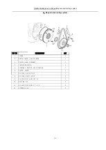
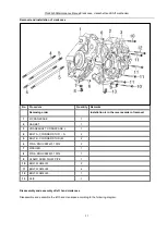
Page 84: ...l 1 R CRANKCASE 1 2 GASKET 1 3 CRANKSHAFT CRANKCASE L 1 4 BOLT A CYLINDER STUD A 2 5 BOLT B CYLINDER STUD B 2 6 PIN A KNOCK92401 10014 2 7 WASHER 1 8 PIN A KNOCK92401 10014 1 9 CLAMP OVER FLOW PIPE 1...

Page 85: ...Replace oil seal with a new one after being removed Notice Do not dent the sealing surface and assemble the driving shaft bearing with the side with oil seal facing inwards No Procedure Quantity Remar...

Page 86: ...he needle bearing may damage it in case it is damaged always change a new one Replace washer with new ones after being removed Apply the thread retaining adhesive LOCTITE 648 while assembling the stud...

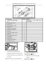
Page 87: ...in the reverse order of removal 1 Left hand crankcase 1 2 Crankshaft 1 3 Knock pin 2 4 GASKET 1 Disassembly and assembly of crankshaft and balance shaft Do not further disassemble the crankshaft other...

Page 88: ...NG 1 h SUPPORT SPRING START 1 i WASHER 17 1 j WASHER 20 2 k SHAFT KICK STARTER 1 l CIRCLIP 20 2 1 27 1 Crankshaft and balance shaft inspection 1 Check whether the crankshaft journals are abnormally wo...

Page 89: ...ariable transmission system 1 Place the right hand crankcase assembled with crankshaft and balance shaft on the assembly operating table and the driving driven shaft and assemble the them together 2 A...

Page 90: ...hile assembling No Procedure Quantity Remarks Sequence of disassembling Assembling is in the reverse order of disassembling 1 SPRING 1 2 FIXING PLATE 1 3 BOLT M8 35 1 4 BOLT M6 12 1 i PRESS BOARD SWIC...

Page 91: ...k is bent and whether the gearshift drum guiding slot is damaged Measure the shift fork claw thickness Maintenance limit 4 86mm Warning Thread retaining adhesive LOCTITE243 must be applied to the roto...

Page 92: ...YG48Q 5AMaintenance ManualFrame and exhaust system 105 10 Frame and exhaust system...

Page 93: ...ouble symptom of component Trouble symptom of motorcycle Repair method Frame The frame is deformed or broken The frame is deformed or broken Running off tracking Calibrate or replace frame Main stand...

Page 94: ...ng bolts in the headlamp bracket Pull off the headlamp patch plug to remove the headlamp Instrument Remove the meter assembly total of 3 connecting bolts And remove the connection cable To mount the c...

Page 95: ...Replacement of turn lamp bulb Loosen the screws remove the lamp lampshade Lightly press bulb rotate in counter clockwise Install new bulb in opposite order as below Front and rear lamp bulb12V1 5W Ta...

Page 96: ...ler seal gasket at the engine s exhaust port shall be replaced with a new one While mounting apply sealants at the joining part of the exhaust pipe and the muffler and fasten the bolts of the exhaust...

Page 97: ...YG48Q 5A Maintenance ManualFront wheel front overhang and steering stem 110 11 Front wheel front suspension device and steering stem...

Page 98: ...que values Front wheel spindle 50N m 60N m Steering handle set bolt 20 30 N m Front fork vertical pipe cap nut 50 60 N m Upper lower connection plate set bolt 8 12 N m Brake disc fastening nut 20 30N...

Page 99: ...steel cable The steel cable The clutch is slipping or not fullydisconnected Replace control steel cable Rear brake pedal The free stroke is over small The clutch is not fully disconnected Readjust the...

Page 100: ...ce front shock cylinder Piston rod Over worn or damaged Over soft at front shock cylinder Replace piston rod Piston ring is over worn ordamaged Over soft at front shock cylinder Replace piston ring Oi...

Page 101: ...into oil pipe brake lose effect exhaust front brake oil way oil pipe is broken oil leakage from oil pipe brake lose effect replace oil pipe frontbrake oil pipe is clogged oil pipe is clogged brake los...

Page 102: ...move the Left combination switch Remove the right brake cylinder body Remove the clutch control line and disassemble the connection of the clutch switch leads Remove the right combination switch Loose...

Page 103: ...n board and then the bolt at direction of the tube up to the torque of 20 30N m 4 Do not mount the throttle cable in the opposite direction of the feeder on the right handle otherwise the handle may r...

Page 104: ...Place the front wheel spindle on the V holder and measure the deflection of the wheel spindle with a dial gauge if the reading is no less than 0 2mm replace the front wheel spindle Front wheel bearing...

Page 105: ...he tightening torque being 20 30 N m Check 1 Dismantle oil drain bolt and check bolt whether or not is loose 2 Drain off absorber oil and check quality whether or not is turned 3 Take off dust sleeve...

Page 106: ...le Refer to the related sections 2 Remove the upper connect plate To mount of steering stem Installation is in the reverse order of removal While installing the steering stem adjust the adjusting nut...

Page 107: ...ately instead drive it after holding and releasing the front brake handle until the brake strip and the brake disc are well engaged Front brake disc inspection Measure the thickness of the brake disc...

Page 108: ...YG48Q 5A Maintenance ManualRear wheel and rear suspension device 121 12 Rear wheel and rear suspension device...

Page 109: ...damper reliably stand the motorcycle from under the engine a jack or other supports Key torque values Real wheel spindle nut 50 60 N m Rear fork shaft nut 50 60 N m Troubleshooting Rear wheel shimmy...

Page 110: ...cription Damage form Trouble symptom ofcomponent Trouble symptom of motorcycle Repair method Sprocket and cam sprocket Gear is over wor Drive chain has abnormal sound drive chain is easy to fall out R...

Page 111: ...k is between 20mm and 30mm and that the left and right scale lines of the chain adjuster are consistent and then fasten the rear wheel spindle nut to the required tightening torque of 60 90N m Warning...

Page 112: ...r axle lock nut and remove the rear fork shaft from the left side 3 Remove the rear damper and rear fork connecting bolt 4 Take out the rear fork backwards To install the rear fork Installation is in...

Page 113: ...r installation of the damper Notice Before removing the damper the tightening torque of the bolt connecting the frame is 30 40N m and the tightening torque of the bolt connecting the rear fork is 30 4...

Page 114: ...instead drive it after holding and releasing the front brake handle until the brake strip and the brake disc are well engaged Rear brake disc inspection Measure the thickness of the brake disc with an...

Page 115: ...here the removal is convenient first following the principle of searching from easy to difficulty Both the parameter detection method and the parts replacement method are acceptable However if the par...

Page 116: ...ms The main contents include recharging charge storing and discharging YG48Q 5A power supply features large power supply capacity as high as more than 250W It comprises the following parts and compone...

Page 117: ...low wire whether is short circuit or broken circuit by millimeter 3 Open left cover to check magneto coil whether is burned or loose 4 Dismantle magneto bolt and replace magneto coil 5 Dismantle start...

Page 118: ...accumulator s terminal voltage is less then 12V The vehicle has been stored for too long and the accumulator has discharged automatically Charging circuit fails in the complete vehicle Accumulator fa...

Page 119: ...on of shift position switch side stand switch and clutch switch then press down the start button to power on the relay start the engine to drive the idle gear and starter gear thus enabling the engine...

Page 120: ...whether is charged 5 Check fuse whether is burned 6 Check positive and negative pole of battery whether contact well 7 Check relay whether is damaged 8 Check magneto coil whether contact well 9 Check...

Page 121: ...ce clutch switch Connect the line or replace the left switch Connect the line or replace the left switch Replace the starting relay Repair or replace main cable Starting motor doesn t rotate there is...

Page 122: ...es and people to dodge by the flash of the turn lamp while driving at night it shall inform of its presence by the tail lamp s front rear position lamp and illuminate the number on the license plate w...

Page 123: ...YG48Q 5A Maintenance ManualIllumination signal system 136 Circuit schematic drawing...

Page 124: ...ther is charged 5 Check fuse whether is burned 6 Take off headlamp switch socket to check whether there is current 6 Dismantle headlamp bolt to check lamp case whether is damaged 7 Mount bulb and hold...

Page 125: ...lose contact Adjust velum of electrical horn to check it whether is damaged 16 Check neutral socket whether contact well 17 Signal lamp control systems Check flasher whether is burned or plug is loos...

Page 126: ...YG48Q 5A Maintenance ManualIllumination signal system 139...

Page 127: ...elated lines of the main cable are open Connect the fuse or replace it Repair or replace the left switch Replace bulb Re plug Repair or replace main cable Brake lamp does not illuminate Corresponding...

Page 128: ...n theYG48Q 5Adisplays include vehicle speed engine speed fuel indicator Neutral indicator turn indication high beam indication total subtotal mileage traveled and EFI Indicator Constituting parts and...

Page 129: ...ng to assure safe riding 2 Odometer Indicate riding distance Km 3 Turn indicator R right turn twinkle when turn to right Green L left turn twinkle when turn to left Green 4 Headlight high beam indicat...

Page 130: ...dlamp holder to check holder whether there is current 4 Dismantle meter bolt to check it whether is loose or damaged 5 Dismantle meter bolt and odometer cable to check bolt whether is damaged or loose...

Page 131: ...cation failure Line poorly plugged or open circuit Meter failed ECU failed Re plug or repair Replace meter Replace ECU Fuel level indication failure No indication while there is fuel Having indication...

Page 132: ...handled Through the engine and actuators on the vehicle ignition coil fuel injector Idle speed control valve and so on the fuel and fire are exactly controlled and corrected with closed loop For produ...

Page 133: ...YG48Q 5A Maintenance ManualEngine management system 146 Major parts and components...

Page 134: ...YG48Q 5A Maintenance ManualEngine management system 147...

Page 135: ...2 Turn the ignition off before connect or disconnect the connectors 3 Make sure the temperature of the ECU is below 80 4 The fuel pressure is much high about 250kPa so please do not disassemble the fu...

Page 136: ...oltage KsDGDM_IAT_ShortLow P0113 IAT Circuit High Voltage or Open KsDGDM_IAT_ShortHigh Coolant Oil Sensor P0117 Coolant Oil Temperature Sensor Circuit Low Voltage KsDGDM_CoolantShortLow P0118 Coolant...

Page 137: ...the data of intake air temperature equals to the real intake air temperature Yes Setp 5 No Next 3 Remove the connector and use the multimeter to check whether the resistance between pin B and D is rea...

Page 138: ...tion on Next 2 check whether the data of engine temperature equals to the real temperature Yes Step 5 No Next 3 Remove the connector and use the multimeter to check whether the resistance between pin...

Page 139: ...0123 Information TPS Circuit High Voltage ITEM OPERATION RESULT NEXT STEP 1 Connect the diagnostic tool and ignition on Next 2 Check whether the data of Throttle opening is between 0 1 Yes Step 5 No N...

Page 140: ...PR Coil Circuit Low High Voltage or Open ITEM OPERATION RESULT NEXT STEP 1 Connect the diagnostic tool and ignition off next 2 Wait about 30s Remove the fuel pump realy ignition on Check whether volta...

Page 141: ...rst before issue analysis Diagnostic Help 1 Make sure there is no any issue record of the engine 2 Make sure the issue could repeat 3 Have checked follow the instructions above and no cause found 4 Do...

Page 142: ...ction is normal Yes Next No Clean or change the injector Pull out the sprk plug check whether it is wet or not Yes dry the plug and combustion chamber No Next Check whether the cylinder pressure is no...

Page 143: ...rness maintenance Check whether the injeoctor is blocked Yes Clean or change the injector No Next Check the typ and the clearance of the spark plug Yes Next No Change the sprk plug Check whether the c...

Page 144: ...YG48Q 5A Maintenance ManualElectrical System Diagram 157 19 Electrical System Diagram...

Reviews: