ASSEMBLY INSTRUCTIONS
ASSEMBLY INSTRUCTIONS
7
8
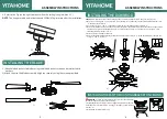
INSTALLING THE LIGHT KIT
1.Remove 3 mounting screws from the light kit.
2.Find the Molex connector from the motor and the Molex connector from the light kit.
Slide them together.
3.Install 3 screws to the junction box of the motor and light kit all securely.
4.Carefully install the crystal shade into the main body and turn it clockwise to lock it.
WARNING
: Take care not to over tighten when installing the glass shade.
WARNING
: To avoid possible electrical shock, be sure the electricity is turned off in the main fuse box before wiring.
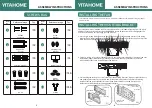
Loosen the 2 screws on the bottom of mounting bracket
but do not remove them. Raise the canopy up and align the
keyholes on the bottom of the canopy with the 2 screws on
the bottom of mounting bracket.
Rotate the canopy until both screws from the mounting
bracket drop into the slot recesses. Tighten screws.
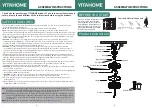
1. Connect the fan to the remote control. The fan’s 4P plug should insert into the the remote control’s
4P plug.
2. Connect the remote control to the house’s power line, then connect the remote control’s white wire
to the house’s white wire. Connect the remote control’s black wire to the house’s black wire, and
connect all the fans’ green ground wires to the house of ground wires. Secure wires.
3. Connect the fan motor to the lamp: connect the fan motor’s 1P white wire to the lamp’s 1P white
wire. Connect the fan motor’s 1P blue wire to the tool’s 1P blue wire.
MAKE THE ELECTRIC CONNECTIONS
INSTALLING THE CANOPY
Motor
green
FOR MOTOR black
O
to
t
he
F
A
N
M
O
T
O
R
to
t
he
F
A
N
L
IG
HT
receiver of
remote
control
4P
to
A
C
P
o
w
er
brown
ACIN
N
AC
IN
L
green
120
Vac
SUPPLY
AC
N
AC
L
blue
green
FOR MOTOR/LIGHT N white
FOR LIGHT L blue
4P
TO MOTOR black
O
TO MOTOR/LIGHT N white
TO LIGHT L blue
green
!
Installation is now finished. Turn on the power switch as Fig 7. Then the fan lights are on. Test and pair your fan
immediately using the remote control.
1
2
3
4


