INST
ALLER'S
INSTRUCTION
BRIEF UNIT INFO
P15 OF 36
P16 OF 36
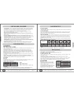
ELECTRICAL DATA
VOLTAGE SUPPLY
Check voltage supply at outlet. For satisfactory results, the voltage range must always be within the ranges found
on the data information plate.
Cord-connected Units
The 250-v field supplied outlet must match the plug for the standard 208/230--v units and be within reach of the
service cord. The standard cord-connected 265-v units require an accessory electrical subbase for operation.
Refer to Table 2 for proper receptacle and fuse type.
Power Cord Protection
The power cord for 230/208v units provide power cord fire protection. Unit power automatically disconnects when
unsafe conditions are detected. Power to the unit can be restored by pressing the reset button on plug head.
Upon completion of unit installation for 230/208V models, an operational check should be performed using the
TEST/RESET buttons on the plug head.
NOTE:
The 265v models do not incorporate this feature as they require use of the electrical subbase accessory.
RECEPTACLES AND FUSE TYPES - 250, 265 VOLTS
LEGEND
HACR - Heating, Air Conditioning, Refrigeration * May be used fro 15 - amp applications
Proper installation is the responsibility of the installer.
Product failure due to improper installation is not covered under the Warranty.
INSTALLATION
Units are shipped without a sleeve. In applications where unit is a replacement, it is recommended that a YMGI
or Carrier sleeve be used.
These units can retrofit General Electric, Amana, Trane, and Friedrich sleeves/grilles (be sure outdoor
grille is installed on the sleeve). See Table 3 for details.
For any sleeve retrofit applications, be sure that the foam seals (factory--installed on the tube sheets) provide a
good seal between the grille and outdoor coil tube sheets. These foam seals provide a barrier to separate
outdoor coil leaving air from mixing with the outdoor incoming air (known as air reticulation).
CHASSIS INSTALLATION
UNIT DAMAGE AND/OR OPERATION HAZARD
Failure to follow this caution may result in equipment
damage or improper operation.
For retrofit applications, foam seals on outdoor coil
tube sheets must make a seal between the coil and
the grille or loss of performance and premature
damage to the major components can result.
RetrofitWall Sleeves
* FR - SLEEVE - EXT accessory is required for retrofit into
Friedrich (T - Series) wall sleeves.
Manufacturer
Wall Sleeve Part Number
General Electric
Metal Sleeve RAB71
Plastic Sleeve RAB77
Amana
Metal Sleeve WS900B
Trane
Metal Sleeve SLV149
Friedrich
T - Series Metal 111/2 - in. Deep Wall Sleeve*
Standard Depth Wall Sleeve 16 X 42 X 133/4 - in. PXWS
AMPS
15
20
30
15
20
30
RATED VOLTS
250
250
250
265
265
265
TIME-DELAY TYPE FUSE
(or HACR Circuit Breaker)
15
20*
30
15
20
30
RECEPTACLE
UNIT FEATURES CONTINUED
* Unit Configuration
- There are many different configuration possibilities, through both dips witches and the
digital keypad, that allow you to configure the unit for your exact application. See section on unit configuration
for more details. Following are the configuration selections that have-not previously been mentioned:
* Limit the Set point Range
- The unit can be configured to limit the controlling set point range. The display will
always show the complete set point range, but the controlling set point will be limited to the configured
minimum and maximum set point selected. See section on unit configuration for more details.
O
O
O
O
* F or C
- The unit can display in either F or C. Spell out (Fahrenheit) or (Celsius).
* Indoor Temperature Sensor Biasing
- Optimize the room temperature sensor reading to your exact
application (one for cooling and another for heating)..
* Emergency heat (for heat Pump Only)
- Disable the compressor during heating mode operation (heat only
with Electric Heat).
* Display Set point OR Room Temperature
- The unit can be configured to display the room temperature OR
set point only, during heating and cooling modes. See section on unit configuration for more details.
* Energy Management
- Sometimes known as Front Desk Control, an input is provided so that the unit can be
manually disabled from a different location. If the unit detects 24vac on this input, it will automatically turn itself
off. If no voltage is detected on the input, the unit will run normally.
* Wall Thermostat Control
- A wired wall thermostat can be connected to the unit. If it is, the unit must be
configured to disable the keypad. See section on wired inputs and unit configuration for more details.
ELECTRICAL SHOCK HAZARD
Failure to follow this warning could result in personal injury or death and/or property damage DO NOT alter cord
or plug or use an extension cord.
Appropriate power cord accessory kit is determined by the voltage, and amperage of the branch circuit.
The unit does not come with a power cord (or hard wire kit). An accessory power cord kit must be ordered to
connect the unit to the outlet. If the unit is to be hard wired, an accessory hard wire kit must be ordered.
IMPORTANT: For 265V units, if power cord accessory option is selected, the cord is only 18" long and
must plug into the accessory electrical 265V subbase.
Be sure that your outlet matches the appropriate blade configuration of the plug and that it is within reach of the
service cord.
All wiring, including installation of the receptacle, must be in accordance with the NEC and local codes,
ordinances and regulations. National codes require the use of an arc fault or leakage current detection device on
all 208/230V power cords. Be sure to select the correct cord for your installation.
ALL UNITS
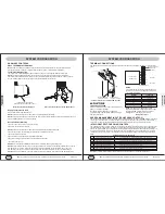
Wire Size
Use recommended wire size given in Table 1 and install a single branch circuit. All wiring must comply with local
and national codes. All units are designed to operate off ONE single branch circuits only.
NOTE: Use copper conductors only.
LEGEND
AWG - American Wire Gauge
* Single circuit from main box.
O
* Based on copper wire at 60 C temperature rating.
SUGGESTED BRANCH CIRCUIT WIRE SIZES*
NAMEPLATE AMPS
AWG WIRE SIZE
7.0 to 12
12.1 to 16
16.1 to 24
14
12
10
Grounding
For safety and protection, the unit is grounded through the service cord plug or through separate ground wire
provided on hard wired units. Be sure that the branch circuit or general purpose outlet is grounded.
ELECTRICAL DATA
YMGI, Engineered Comfort Products for A Sustainable and Efficient Green World !
YMGI, Engineered Comfort Products for A Sustainable and Efficient Green World !


