background image

UNIT MAINTENANCE & 

SER

VICE GUIDE

INST

ALLER'S 

INSTRUCTION

P29 OF 40

P30 OF 40

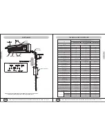
Heat insulator (indoor unit)

Interconnection cable

Sealing tape

Ribbon vinyl

Heat
insulator
 (connection
pipe)

Sealing tape

Join the tubes insulators and refrigerating 
connection so as there is no space.

Interconnection cable

Drain hose

Drain hose

PiPe

PiPe

Clamp

Pipe

Interconnection cable

RIibbon viyl

Wall

Out

Outdoor screw

Putty

Overlap nylon ribbon
or similar wrap.

Pipe of indoor unit

Connecting pipe

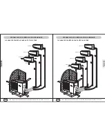
Seal Copper Line Set/Wire Cable/Drain Hose Line Combination

* Run cables along with the refrigerating copper line sets and secure them with tapes at 6 feet apart.

* Wrap tape closely (cover a third of the width of the nylon ribbon tape applied early) to get good seal.

* Tape to seal the end of taping.

* Shape the pipe combination gently, without causing kinking, sharp bending, or other damage to it.

* Fix the pipe combination securely on the external wall with proper clamps, as drafted below, at 6 feet apart.

* Fill the gap between the wall hole and wall sleeve with putty to keep from rain or dust getting inside.

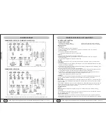
CONNECT REFRIGERANT PIPES BETWEEN INDOOR AND OUTDOOR UNITS

PIPING GUIDE

To keep the allowed bending 
radius, please make the 
packed soft pipes vertical for 
expanding.

Please do not expand 
only one side of the 
packed soft pipes.

Please make use of 
semicircle pulley to keep 
the allowed bending 
radius.

Please use twisting 
wheel to avoid improper 
bending.

Please use rigid elbow 
to keep the bending 
radius while soft pipes 
operating.

Please keep the 
minimum bending 
radius while installing.

Extremely bending could 
damage the pipes.

Over length soft pipes 
will lead to irregular 
bending.

Undersize bending will 
damage the soft pipe.

Short soft pipes will 
have them bending 
undersize, it's not 
allowed.

YMGI, Engineered Comfort Products for A Sustainable and Efficient Green World !

YMGI, Engineered Comfort Products for A Sustainable and Efficient Green World !

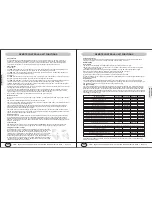
CONNECT REFRIGERANT PIPES BETWEEN INDOOR AND OUTDOOR UNITS

Firstly, connect copper tubes at indoor unit. Bend 
pipes by tools but not by hands. Extra length is 
needed for future service.

REFRIGERANT PIPES: 

For distance other than 25' between indoor and 
horizontal venting condensing units, refer to the 
following table for copper sizes.

Make sure the pipe section where is to be cut is 
straight and smooth. Apply cutting blade straightly 
perpendicular to the pipe surface. Don't cut too fast 
or too hard. Turn and tighten the tube cutter slowly. 
Remove residual left at the cutting edge. The cutting 
edge should be clear and clean and smooth.

Running Interconnection Refrigerant Lines: 

Use clean refrigeration grade of copper tubing only. 
Keep the copper lines from kinking and transmitting 
noise to walls, cabinets, etc. Not to exceed 100' with 
35' of vertical lift included. Insulate the suction line 
with at least 3/8" thick insulation tubes. Band and 
tape and secure refrigerant lines. Support copper 
lines at proper distance apart to keep tubes from 
sagging.

CUT REFRIGERANT PIPE:


Connect Copper Pipes-Flare/nut Connection at Both Indoor and Outdoor Units

Proper torque shall be applied to make good connection at female nut, flare and male nut, as recommended in 
the following table. Too much torque may damage and break flare/nut seal. Too less torque may not ensure 
good seal. ALWAYS use a pair of wretches.

Flare Nut

1/4-3/8"

1/4-1/2"

1/2-3/4"

7/8-1 1/8"

Tightening Torque

25 Ft. LBs (350 Kgf.cm)

40 Ft. LBs (560 Kgf.cm)

60 Ft. LBs (840 Kgf.cm)

110Ft. LBs (1540 Kgf.cm)

Refrigerant Pipe Flare/Nut Connection Tightening Torque

Refrigerant Pipe Length and Height 

CONNECT REFRIGERANT PIPES

In this case, put wet rag to protect valves or other components from being overheated. When using flux, rub the 
tube surface using steel wool to shine and clean to dry as so to keep to-be-sealed system from any possible 
contamination.

Connect Copper Pipes-Sweat Connection

Refrigerant Valve and Pipe Size/Length

K

Btu/h

09

12

18

Valve Size

Liq, Gas

1/4", 3/8"

1/4", 3/8"

1/4", 1/2"

15-30ft

1/4", 3/8"

1/4", 3/8"

1/4", 1/2"

31-60ft

1/4", 3/8"

1/4", 3/8"

1/4", 1/2"

Line Sizes at Different Length

1,000 Btu/h

09

12

18

 Height (Ft.)

3.82

3.6

3.8

Length (Ft.)

23

24.3

31.4

Summary of Contents for WMMS-09EW-V2B

Page 1: ...pment NEC State City or Local Codes and related manuals from us Otherwise damage to equipment or property even injury to people may occur Installer Currently licensed HVAC installer only Read this man...

Page 2: ...ory labs third party labs and various fields applications following related industrial and company standards 7 Field installation details matter with all 1 if your units will work correctly and proper...

Page 3: ...ty approval because warranty is approved only to those qualified and successful installations by qualified HVAC technician I know the warranty if approved is a standard 5 year compressor and 1 year ot...

Page 4: ...eral knowledge and experience a full single head installation may normally cost anywhere from 800 to 1500 These costs are estimates and your actual costs may differ due to job nature and location 8 Nu...

Page 5: ...D MUST READ MUST READ P7 OF 40 P8 OF 40 YMGI Engineered Comfort Products for A Sustainable and Efficient Green World YMGI Engineered Comfort Products for A Sustainable and Efficient Green World The co...

Page 6: ...t Green World YMGI Engineered Comfort Products for A Sustainable and Efficient Green World If the damage is minor or partial that you choose to accept you can contact the distributor or YMGI to discus...

Page 7: ...he Customer Request to Ship Products to YMGI Service Center for Inspection and Repair and Authorization to Charge form 2 You will review the form and fill all fields appropriately sign and send back t...

Page 8: ...copper tube Aluminum fin copper tube Swing Motor Model MP28VB 1 4 3 8 MP28EC MP35XX Output of Swing Motor W 2 2 2 5 Fuse A PCB 3 15A Transformer 0 2A PCB 3 15A Transformer 0 2A PCB 3 15A Transformer 0...

Page 9: ...WS DIMENSIONS MOUNING BRACKET CLEARANCE YMGI Engineered Comfort Products for A Sustainable and Efficient Green World YMGI Engineered Comfort Products for A Sustainable and Efficient Green World WMMS 0...

Page 10: ...this mode only indoor fan is running at setting status Under auto fan speed it will run by cooling auto fan Heating Mode When the indoor receiving the information mode clash from outdoor unit and the...

Page 11: ...ter setting sleep procedure 1h T preset will increase 1 F 2h later T preset will O O increase 2 F then remain the temperature T preset will not exceed 86 F under heating after setting sleep O O proced...

Page 12: ...ER 4 OVER 80 CLEARANCE REQUIRED AROUND UNITS DUAL ZONE 2 YMGI Engineered Comfort Products for A Sustainable and Efficient Green World YMGI Engineered Comfort Products for A Sustainable and Efficient G...

Page 13: ...E REQUIRED AROUND UNITS QUAD ZONE OVER 2 OVER 4 OVER 4 OVER 80 YMGI Engineered Comfort Products for A Sustainable and Efficient Green World YMGI Engineered Comfort Products for A Sustainable and Effic...

Page 14: ...for screws Align mounting plate holes with those holes drilled on the wall and put anchors or screws into the holes to secure mounting plate Steps To Mount Plate a b c Drill mounting holes to make su...

Page 15: ...ipes need to come out of the bottom side facing the front of indoor unit of the indoor unit snap off portion 2 on plastic casing If pipes need to come out of the left side facing the front of indoor u...

Page 16: ...N INDOOR AND OUTDOOR UNITS Firstly connect copper tubes at indoor unit Bend pipes by tools but not by hands Extra length is needed for future service REFRIGERANT PIPES For distance other than 25 betwe...

Page 17: ...25 26 27 28 29 30 Jumping connector 1 32 Transformer 48X26P 1 33 Wire clamp 1 34 Rear clamp 1 35 Connecting cable 1 36 swing louver clamp 1 37 swing louver 1 38 swing louver up 1 39 swing louver down...

Page 18: ...e 68012019 1 Receiver board 30545042 1 Front panel 200022921 1 Guide louver 261120432 1 Guide louver 261120422 1 Motor MP28EC 15212002 1 Right motor clamp 26112429 1 Bearing holder 26152423 1 Motor FN...

Page 19: ...2 Front case 200026524 1 Front panel 2000284402 1 remote control YT1F 30510049 1 Displaying light board 22432071 1 Electric box cover 1 20112019 1 Wire clamp 71010103 1 Terminal board 4201026601 1 El...

Page 20: ...mfort Products for A Sustainable and Efficient Green World DISASSEMBLY PROCEDURE OPERATING PROCEDURES PHOTOS Disassemble Front Panel Lift the front panel upward Firstly screw off a screw fixing the up...

Page 21: ...ny damages to person or property of whatever kind direct or indirect special or consequential whether resulting from use or loss of use of the product The original licensed installer or current servic...

Reviews: