App-4
IM 2558A-01EN
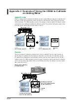
Appendix 3 Example of Using the 2558A to Calibrate
a Power Meter
To calibrate a power meter, two 2558As are used: one for voltage output and another for current
output.
In addition, a Precision Power Analyzer of WT3000E series is used as a reference power meter.
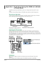
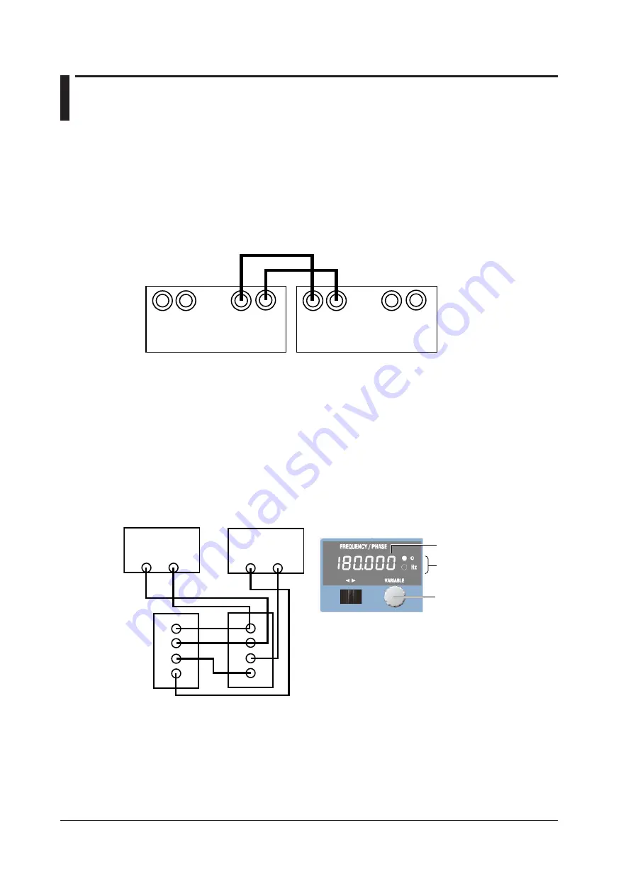
Synchronous Operation
To synchronize the voltage and current outputs, one 2558A is used as a master device to transmit a
synchronization signal to the other 2558A (slave). See sections 2.6 and 5.2.
Setup example: Frequency set to 60 Hz
2558A (master)
2558A (slave)
Q(sin)
I(cos)
Setup example: Frequency set to EXT2
EXT 1
OSC OUTPUT
EXT OSC INPUT
I
I
Q
Q
EXT 1
OSC OUTPUT
EXT OSC INPUT
I
I
Q
Q
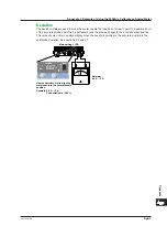
Adjusting the Phase Angle
Connect the reference power meter and the power meter under calibration as shown below. Set
appropriate ranges and values on the master and slave devices. Turn the output on, and adjust the
phase difference between the voltage and current outputs. Adjust the phase angle on the slave 2558A.
Turn the VARIABLE dial on the slave 2558A so that the power factor of the reference power meter is at
the calibration point. See sections 2.2 and 5.2.
2558A (master)
Setup example:
Set RANGE to 100V.
Voltage output
terminals
2558A (slave)
Setup example:
Set RANGE to 10 A.
Current output
terminals
Reference
power meter
(WT3000E)
U
±
I
±
HI
LO
HI
LO
Unit
The specified phase angle
Set the phase angle (value).
Power meter
under calibration
U
±
I
±
Calibration
Apply the same voltage and current to the reference power meter and the power meter under
calibration.
Use the voltage, current, and phase values on the reference power meter, not the 2558A.