1-1
IM 2558A-01EN
Component Names and Functions
3
2
1
4
5
6
7
8
9
10
11
12
13
14
15
16
App
Index
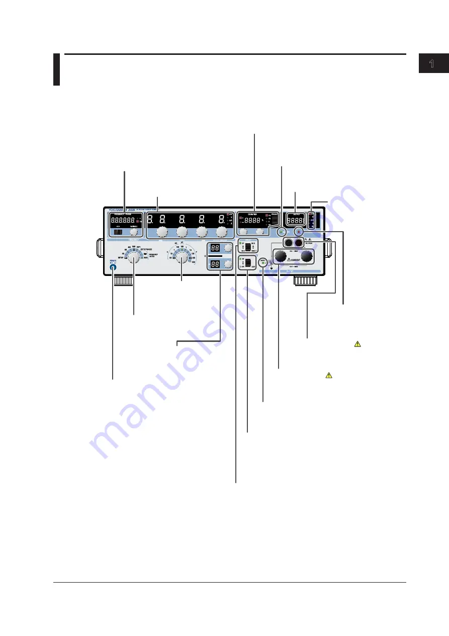
1.1 Panel
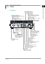
Front Panel
Current terminals
Used to connect the included
measurement leads
→ Section 3.6
Voltage terminals
Used to connect the included
measurement leads
→ Section 3.6
LO TO EARTH indicator
Indicates the grounding state of the LO terminal.
Illuminates when SETUP EARTH is on
→ Section 5.1, and 6.1
SWEEP section
Performs up or down sweeps
→ Sections 1.2, 5.8, and 6.8
Power switch
Turns the output on and off
→ Section 3.4
OUTPUT section
Turns the voltage or current output on and off
→ Sections 1.2, 5.6 and 6.6
Switches remote mode (controlled through
communications) to local mode
→ Sections 9.1, 10.1, and 11.1
FREQUENCY dial
Switches the frequency
→ Sections 5.2 and 6.2
OUTPUT DIVIDER section
Divides the voltage or current
level or the frequency output
→ Sections 5.5 and 6.5
RANGE dial
Switches the voltage or
current range
→ Section 5.3 and 6.3
OUTPUT indicator
Displays the voltage, current, or frequency.
→ Sections 5.6 and 6.6
Output unit indicator
Displays the output unit.
HIGH VOLTAGE indicator
Illuminates when the RANGE dial
is set to 300 V or 1000 V
→ Section 5.3 and 6.3
FREQUENCY/PHASE section
Sets and displays the frequency or phase angle
→ Sections 1.2, 5.2, and 6.2
Main setting section
Sets and displays the voltage or current level.
→ Sections 1.2, 5.4, and 6.4
DEVIATION/PRESET section
Finely adjusts the output value
→ Sections 1.2, 5.7, and 6.7
REMOTE indicator
Illuminates when the 2558A is in remote
mode (controlled through communications)
→ Sections 9.1, 10.1, and 11.1
Chapter 1
Component Names and Functions

