1. System installation requirements
1-6
TI 30A30A10-01EN
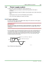
The system operating voltage range is shown below based on the relationship between effective
and peak values at the power input terminal of each system. Apply AC power within these ranges
to operate the system.
TIP
Average rectified measuring meters such as testers cannot measure effective values accurately. Use Yokogawa’s
WT series power meter or an meter, which enables effective values, peak values, and waveform distortion to be
measured with one unit.
120
125 127
90
100
110
120
132
130 140
150
160 170
187
Peak value (V op)
V
V
Effective
value
(V rms)
Effective
value
(V rms)
System operating
voltage range
F010202.ai
274
200
198
220
240
264
280
310
340
370
374
Peak value (V op)
V
V
180
System operating
voltage range
V op= 2 V rms
V op= 2 V rms
Figure System operating voltage range
n
Selecting a power system
N-IO field enclosure system requires a power supply that satisfies power requirements in
accordance with EMC regulations. For selection of the power supply unit, consult with a power
unit manufacturer taking the following points into consideration.
l
Source output capacity
Take the following items into consideration when consulting with a power unit manufacturer to
determine the output capacity.
Power consumption:
Both volt-ampere and watt data should be studied
(refer
to
Chapter
4).
Device in-rush current:
See Chapter 4 Table “System equipment power-on
In-Rush current” The method of turning on the power
should
also
be
studied.
Backup ready time after failure:
Time period required to backup the devices when power
fails.
Reserve capacity:
An extra power capacity should be determined as
reserve to meet any device additions.
Feb. 26, 2018-00

