IM CL235
1
1. Instrument Layout
(1)
(2)
(3)
(4)
(5)
(6)
(7)
(8)
(10)
(9)
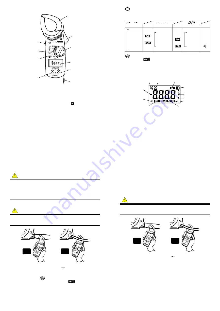
(1) Transformer Jaws : Pick up current flowing through the conductor.
(2) Open/Close Lever : Operates the transformer jaws. Press to open the
Transformer Jaws.
(3) Function Selector Switch : Selects function. It is also used to turn power
on.
(4) Data Hold Button : Freezes the display reading. "
" is shown on the
display when Data Hold is enabled.
2
IM CL235
(5)
Mode Selector Button : Selects measuring mode. Press this switch
to cycle through measuring modes. The instrument is in the normal (NOR)
after it is powered up. In any mode, pressing this switch for more than one
second returns the instrument to the NOR mode.
A /
V
(ACA/ACV)
Display
A/
V
(DCA/DCV)
Display
(Resistance/Continuity) Display
Normal
↓
Average
↓
Peak
↓
Frequency
Hz
Normal
↓
Average
↓
Peak
Resistance
↓
↓
↓
Continuity
check
Ω
(6)
Button : Used for zero adjustment on DCA and resistance ranges.
On DCA range, "
" is shown on the display to indicate auto-zeroing is
completed. This switch is also used to reset the display reading in the
Peak mode.
(7) LCD Display : Field effect type of liquid crystal display with maximum
counts of 3999. Function symbols and decimal point are displayed ac-
cording to selected function and mode.
AC
DC
Average mode
Data hold
Resistance
Voltage
Ampere
Low frequency input
Negative sign
Continuity check
Low battery warning
Peak mode
DCA auto zero
(8) Hi Terminal : Accepts the red test lead for voltage or resistance measure-
ment.
(9) Lo Terminal : Accepts the black test lead for voltage or resistance meas-
urement.
(10) Safety Hand Strap : Prevents the instrument from slipping off the hand
during use.
IM CL235
3
2. Measurement
2.1 Preparation
for
Measurement
CAUTION
●
The jaw section is a delicate, precision sensor. Do not subject the jaw to
unreasonably strong shock, vibration, or force when using it.
●
If dust gets into the tops of the jaws, remove it immediately. Do not close
the jaws when dust is trapped in its joints as the sensor may break.
●
Please check that the range and mode are set to the desired position
before measurement.
2.2 DC Current Measurement
WARNING
●
Do not make measurement on a circuit above 600VDC. This may cause
shock hazard or damage to the instrument or equipment under test.
●
Do not make measurement with the test leads plugged into the instrument.
Correct
Wrong
(1) Set the Function Selector switch to the "
A" position. "DC" should be
shown on the upper left corner of the display.
(2) With the transformer jaws closed and without clamping them onto the
conductor, press the
button for about one second to zero adjust the
display. When zero adjustment is completed, "
" appears on the dis-
play.
(3) Press the open/close lever to open the transformer jaws and clamp them
onto the conductor under test, then take the reading on the display. The
most accurate reading will be obtained by keeping the conductor at the
center of the transformer jaws.
4
IM CL235
NOTE
●
During current measurement, keep the transformer jaws fully closed. Oth-
erwise, accurate measurement cannot be made. The maximum measur-
able conductor size is approx. 33mm in diameter.
●
When the current flows from the upside (the display side) to the underside
of the instrument, the polarity of the reading is positive and vice versa.
●
Turing the Function Selector switch to a position other than DCA cancels
the zero adjustment.
2.3 AC Current Measurement
WARNING
●
Do not make measurement on a circuit above 600VDC. This may cause
shock hazard or damage to the instrument or equipment under test.
●
Do not make measurement with the test leads plugged into the instrument.
Correct
Wrong
(1) Set the Function Selector switch to the "
A" position. "AC" should be
shown on the upper left corner of the display.
(2) Press the open/close lever to open the transformer jaws and clamp them
onto a single conductor and take the reading on the display. The most
accurate reading will be obtained by keeping the conductor at the center
of the transformer jaws.
NOTE
●
During current measurement, keep the transformer jaws fully closed. Oth-
erwise, accurate measurements cannot be taken. Maximum conductor
size is 33mm in diameter.
●
Zero adjustment is not necessary in AC current measurement. There is no
polarity in the reading either.
●
When the current under test measures 3% of the full scale or less, or the
frequency of the current is low, "LoHz" is indicated on the display.


