-26-
3
Before Using the Unit
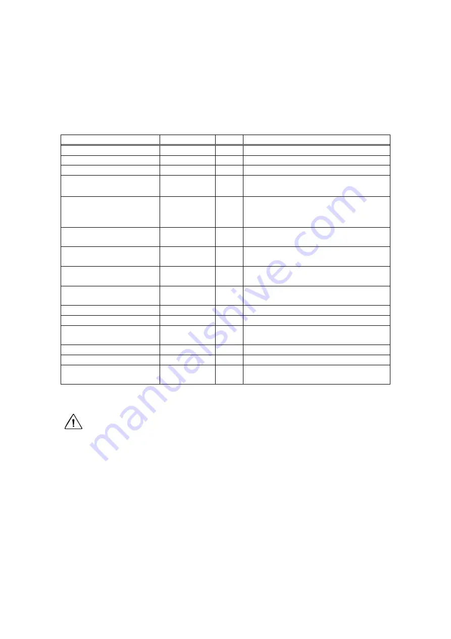
3.1 Packing
List
Part name
Part number QTY Description
CSU-X1 CSU-X1
1
AC adapter
M3916UD
1
Power supply for CSU-X1
Power cable
A1077WD
1
AC adapter cable
Warning label
D8953RH
1
「
Don’t look into the eyepieces when
you change the light pass.
」
Warning label
M3916LK
1
「
LASER RADIATION AVOID
EXPOSURE TO BEAM CLASS 3B
LASER PRODUCT
」
Interlock key for
CSU-X1 unit
M3916HA
1
To control CSU-X1 from the control
panel
Allen wrench
M3916CV
1
For M3 set screw to fix a camera to
C-mount
Bottom port cover
D8953GV
1
For laser output hole, mounted at
factory.
Second port cover
M3916CN
1
For second camera port, mounted at
factory. (Bright Field or two FW type)
Second port cover screws
4
Could be mounted at factory
Camera port *1
M3916JA
1
Camera port of CSU-X1.
Camera port support
M3916CT
1
Support when CSU-X1 is installed at
side port of inverted microscope.
Screw
Y9510ZU
2
To fix M3916CT camera port support
Key Switch
1
Spare key
Optical Fiber
M3916VU
1
Angled 8 degrees polished, AFC
connector
CAUTION
Please only use CSU-X1 specific optical fiber supplied with the CSU-X1 head for the
best optical performance. In case different optical fibers were used, CSU-X1 may
not be able to work at its best optical performance.
Summary of Contents for CSU-X1
Page 1: ...User s Manual Confocal Scanner Unit CSU X1 IM 85A7C25 02E IM 85A7C25 02E 1 Edition...
Page 2: ......
Page 5: ...4 7 4 Control Signal 66 8 Command list 73 9 Warranty 75...
Page 6: ......
Page 15: ...13 Figure 1 3 Positions to attach warning labels to CSU X1 M2 E...
Page 16: ...14 Figure 1 4 Positions to attach warning labels to CSU X1 A2 E...
Page 17: ...15 Figure 1 5 Positions to attach warning labels to CSU X1 A3 E...
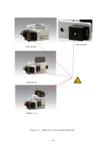
Page 18: ...16 Figure 1 6 Positions to attach warning labels 6 CSU X1 M1 CSU X1 A2 CSU X1 A3 CSU X1 FW...
Page 19: ...17 Figure 1 7 Examples of warning labels attached to the microscope...
Page 39: ...37 3 3 4 Connection Diagram CSU X1 A1 CSU X1 A2 Microscope Camera Microscope Camera...
Page 67: ...65 7 3 6 CSU X1CU 7 3 7 CSU X1FW Unit mm Unit mm...
Page 78: ......
Page 79: ...User s Manual CSU Control Unit CSUX1CU IM 85A7C26 02E IM 85A7C26 02E 1st Edition...
Page 80: ......
Page 82: ......
Page 98: ...18 4 Name and Function 1 2 3 4 5 6 7 8 9 10 11 12 13...
Page 117: ...User s Manual Filter Wheel CSUX1FW IM 85A7C27 01E IM 85A7C27 01E 1st Edition...
Page 118: ......
Page 120: ......
Page 132: ...14 4 Name and function 1 2 3 4 5 9 17 18 19...
Page 140: ...22 6 3 Dimension of CSUX1FW...


