-28-
3.3 Installation
For installation, please follow instructions and installation manual of the microscope,
laser system, fiber coupler, camera, etc.
CAUTION
Do not use a different microscope or laser system from the originally installed
system.
If you need to use a microscope or laser system different from the originally installed
one, please consult Yokogawa Electric Corporation or your local sales representative.
Please strictly follow Class 3B laser safety instructions in manipulating the optical
fiber and optical fiber coupler when you connect to, adjust, or remove from the laser
system or the CSU-X1.
3.3.1 Installation of Microscope
Please follow the instructions given in the user’s manual of the microscope
manufacturer.
For confocal imaging, laser beam emerges from the objective lens to excite
fluorescence of the specimen when CSU-X1 is set to the microscope to output a laser
beam and the microscope’s light path is set for confocal observation. Part of the laser
beam may be reflected at the specimen’s surface, and a reflected laser beam may be
observed. Be careful not to look at the reflected laser beam from the specimen’s
surface, or shield the stage so that it does not go directly into your eyes.
The reflected laser beam goes through the objective lens, and depending on your
light path setting, it may be observed from the eyepiece of the microscope. As the
reflected laser beam may come out from the ocular lens of the microscope, you must
perform the inspection and modification described in Items (1) and (2) on the next
page, and operate the microscope and unit by following the guidelines given below.
In confocal observation, the light observed through the eyepiece of CSU-X1 (Option)
is weak fluorescence from the specimen. The unit is designed in a way that no
reflected laser beam should be observed via the eyepiece if proper barrier filter is
installed.
However when the system is under automatic control, there is a possibility of
leakage of laser beam into the eyepiece, which is extremely hazardous. If you control
the filters from the computer commands, DO NOT LOOK INTO THE EYEPIECE!
NOTE: When incident laser power (488 nm) is 30mW at the end of the fiber, incident
laser power at the objective lens is about 3mW(typical). Assuming the multiple
reflection rate of the cover glass to be 8%, the reflected laser beam could be around
0.24mW, which corresponds to Class II (*) of JIS laser safety standard (488nm, 1mW
Summary of Contents for CSU-X1
Page 1: ...User s Manual Confocal Scanner Unit CSU X1 IM 85A7C25 02E IM 85A7C25 02E 1 Edition...
Page 2: ......
Page 5: ...4 7 4 Control Signal 66 8 Command list 73 9 Warranty 75...
Page 6: ......
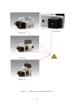
Page 15: ...13 Figure 1 3 Positions to attach warning labels to CSU X1 M2 E...
Page 16: ...14 Figure 1 4 Positions to attach warning labels to CSU X1 A2 E...
Page 17: ...15 Figure 1 5 Positions to attach warning labels to CSU X1 A3 E...
Page 18: ...16 Figure 1 6 Positions to attach warning labels 6 CSU X1 M1 CSU X1 A2 CSU X1 A3 CSU X1 FW...
Page 19: ...17 Figure 1 7 Examples of warning labels attached to the microscope...
Page 39: ...37 3 3 4 Connection Diagram CSU X1 A1 CSU X1 A2 Microscope Camera Microscope Camera...
Page 67: ...65 7 3 6 CSU X1CU 7 3 7 CSU X1FW Unit mm Unit mm...
Page 78: ......
Page 79: ...User s Manual CSU Control Unit CSUX1CU IM 85A7C26 02E IM 85A7C26 02E 1st Edition...
Page 80: ......
Page 82: ......
Page 98: ...18 4 Name and Function 1 2 3 4 5 6 7 8 9 10 11 12 13...
Page 117: ...User s Manual Filter Wheel CSUX1FW IM 85A7C27 01E IM 85A7C27 01E 1st Edition...
Page 118: ......
Page 120: ......
Page 132: ...14 4 Name and function 1 2 3 4 5 9 17 18 19...
Page 140: ...22 6 3 Dimension of CSUX1FW...


