-50-
7
Specification
7.1 Product
Specifications
7.1.1 Specifications of CSU-X1 unit
Item Specification
Principle
Dual Nipkow disk spinning scan with a microlens array
Scanning speed
1.Basic model
* Standard 1: 1,800rpm (w/o control unit)
* Standard 2: 1,500
~
5,000rpm
(Max.1000fps, requires control unit)
* High speed: 1,500
~
10,000rpm
(Max.2000fps,requires control unit)
2.High-end model (with control unit)
* Standard: 1,500
~
5,000rpm (Max.1,000fps)
* High speed: 1,500
~
10,000rpm (Max. 2,000fps)
Scan area size
Standard: C mount: X 1, Image size 10×7mm<
Excitation laser range
405
~
647nm
Excitation laser power
50mW > after FC connector (Laser safety Class 3B)
EX (excitation) Filter
1.Standard: None
2.EX Filter Wheel (CSU-X1FW-06P-02)
* Option: Please inquire (EX filter wheel is not directly
attachable to the CSU-X1 body.)
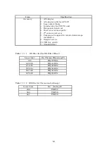
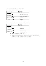
* EX filter line-up is shown in Table 7-1-1.
3. Manual exchange:
* Option: 3 position slider is available, please inquire.
* EX filter line-up is shown in the Tables 7-1-1-1, &
-2.
DM (dichroic mirror
)
1.Standard
:
None
2.Option
:
* Size:13mm×15mm×0.5mm
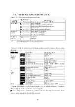
* DM line-up is shown in the Table 7-2-2.
DM exchange
1.Basic model (with & w/o control unit)
* Only CH1 in the DM block is valid.
* DM block can be exchanged manually(*)
2.High-end model (with control unit)
* Three channels are available in a DM block
* DM block can be exchanged manually(*)
(
CAUTION
)
(*) Please ask the advice from your support service for
safely exchanging the dichroic mirror block. Please
comply with the laser Class 3B safety precautions.
Yokogawa standard fiber supplied with the CSU-X1 head
Laser input
Connector
8 degrees polished, AFC connector
Shutter 1.
Response time: 30msec (Not including communication
and overhead of the firmware)
Summary of Contents for CSU-X1
Page 1: ...User s Manual Confocal Scanner Unit CSU X1 IM 85A7C25 02E IM 85A7C25 02E 1 Edition...
Page 2: ......
Page 5: ...4 7 4 Control Signal 66 8 Command list 73 9 Warranty 75...
Page 6: ......
Page 15: ...13 Figure 1 3 Positions to attach warning labels to CSU X1 M2 E...
Page 16: ...14 Figure 1 4 Positions to attach warning labels to CSU X1 A2 E...
Page 17: ...15 Figure 1 5 Positions to attach warning labels to CSU X1 A3 E...
Page 18: ...16 Figure 1 6 Positions to attach warning labels 6 CSU X1 M1 CSU X1 A2 CSU X1 A3 CSU X1 FW...
Page 19: ...17 Figure 1 7 Examples of warning labels attached to the microscope...
Page 39: ...37 3 3 4 Connection Diagram CSU X1 A1 CSU X1 A2 Microscope Camera Microscope Camera...
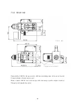
Page 67: ...65 7 3 6 CSU X1CU 7 3 7 CSU X1FW Unit mm Unit mm...
Page 78: ......
Page 79: ...User s Manual CSU Control Unit CSUX1CU IM 85A7C26 02E IM 85A7C26 02E 1st Edition...
Page 80: ......
Page 82: ......
Page 98: ...18 4 Name and Function 1 2 3 4 5 6 7 8 9 10 11 12 13...
Page 117: ...User s Manual Filter Wheel CSUX1FW IM 85A7C27 01E IM 85A7C27 01E 1st Edition...
Page 118: ......
Page 120: ......
Page 132: ...14 4 Name and function 1 2 3 4 5 9 17 18 19...
Page 140: ...22 6 3 Dimension of CSUX1FW...


